2 interior view, Interior view – SMA SB 3300-11 Installation User Manual
Page 22
Advertising
Electrical Connection
SMA Solar Technology AG
22
SB33-38-11-IA-en-62
Installation Manual
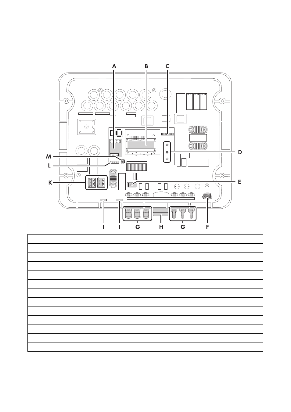
5.2.2 Interior View
The following figure shows the various components and connection areas of the open inverter.
*If you have ordered the inverter without ESS, the inverter is fitted with 2 negative and 2 positive DC connectors.
** optional
Object
Description
A
Slot for communication
B
Display
C
Jumper slot for fan test
D
Operating status LEDs
E
Flat male tab for grounding the cable shield with cable-bound communication
F
AC socket for grid connection
G
DC connectors for connecting the PV strings*
H
Jack for the Electronic Solar Switch (ESS)**
I
Enclosure opening with filler-plug for communication.
K
Varistors
L
Communication connection
M
Jumper slot for communication
Advertising
This manual is related to the following products: