Yaskawa CM092 User Manual
Ethernet/ip option kit cm092, Warning
EtherNet/IP Option Kit
CM092
Yaskawa America, Inc. –
IG.AFD.26, Page 1 of 16
Date: 08/18/2011 Rev: 11-08
Applicable products: Yaskawa F7U, G7U, P7U, E7U, G5M (Spec F),
G5M(600V) and G5HHP drives.
1. Unpack the CM092 EtherNet/IP Option kit and verify that all
components are present and undamaged.
2. Connect power to the Yaskawa AC drive and verify that the drive
functions correctly.
This includes running the drive from the operator keypad. Refer to the
appropriate drive technical manual for information on connecting and
operating the drive.
3. Remove power from the drive and wait for the charge lamp to be
completely extinguished.
Wait at least five additional minutes for the drive to be completely
discharged. Measure the DC bus voltage and verify that it is at a safe level.
4. Remove the operator keypad and drive cover.
a. Remove the operator keypad.
b. Remove the terminal and control covers.
c. Remove the option card hold-down by carefully
compressing the top and bottom until it becomes free
of its holder. Lift it out.
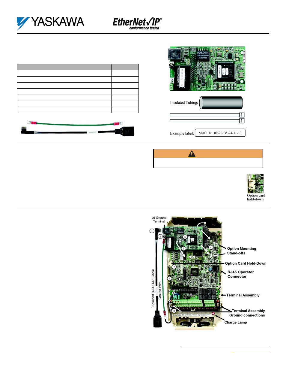
5. Mount the EtherNet/IP Option Card on the drive
Note: Skip to step 6 for G5HHP drives.
a. Connect the RJ-45 M-F cable supplied in this kit to the EtherNet/IP
Option Card.
b. Connect the ground wire supplied to ground terminal J6 on the EtherNet/
IP Option Card.
c. Align the J2 connector on the back of the EtherNet/IP Option Card with
its mating 2CN connector on the drive control card.
d. Align the two standoffs on the front of the drive control board with the
two holes on the right side of the EtherNet/IP Option Card.
e. Press the EtherNet/IP Option Card firmly onto the drive 2CN connector
and standoffs until the J2 connector is fully seated on 2CN and the drive
standoffs have locked into their appropriate holes.
f.
Route the RJ-45 M-F cable and the ground wire along the left-inside of
the AC drive enclosure.
g. Replace the option card hold-down.
h. Connect the ground wire from the option card terminal J6 to the terminal
assembly ground connection.
CM092 EtherNet/IP Option Kit Parts
Qty.
EtherNet/IP Option Card
1
Shielded RJ-45 M-F Cable
1
Ground Wire
1
4" x 1" Insulated Tubing
1
Cable Ties
2
MAC ID Label (Unique for each EtherNet/IP Option Card
1
Installation Guide (IG.AFD.26)
1
WARNING
Dangerous voltages in excess of 400VDC (230V drives) or 800VDC
(460V drives) are present at the DC bus terminals of the drive.