Ethernet/ip option kit cm092, Warning – Yaskawa CM092 User Manual
Page 5
Yaskawa America, Inc. –
IG.AFD.26, Page 5 of 16
Date: 08/18/2011 Rev: 11-08
EtherNet/IP Option Kit
CM092
14. Finish the EtherNet/IP Option Card installation.
a. Remove power from the AC drive and wait for the charge lamp to be
completely extinguished. Wait at least five additional minutes for the
drive to be completely discharged. Measure the AC drive DC bus voltage
and verify that it is at a safe level.
b. Reinstall all drive covers and the operator keypad. Apply power to the
drive.
c. Set parameters b1-01 and b1-02 to their appropriate values.
Refer to the table to the right for available b1-01 and b1-02 values.
15. Resetting the EtherNet/IP Option Card to its default configuration
The factory default settings are as follows:
Configure Network Parameters: DHCP
IP Address:
192.168.1.20
Subnet:
255.255.255.0
Gateway:
192.168.1.1
Symptom: The Yaskawa EtherNet/IP Option Card Main web page does not
display on the PC web browser screen.
Corrective Action: Check that the PC is set up, properly connected and that
an IP address has been assigned to both the server and the node and that they
are on the same local network.
If the web page is still not visible after confirming PC set up, then reset the
configuration of the EtherNet/IP Option Card to its factory default as
follows:
a. Remove power from the AC drive and wait for the charge lamp to be
completely extinguished. Wait at least five additional minutes for the
drive to be completely discharged. Measure the AC drive DC bus voltage
and verify that it is at a safe level.
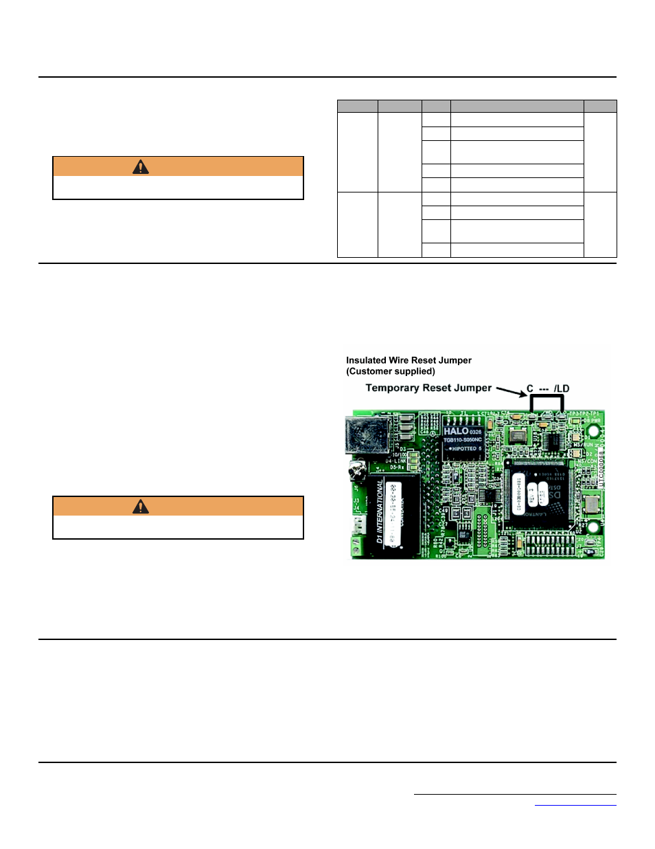
b. Place an insulated wire reset jumper between test points C and /LD on
the EtherNet/IP Option Card as shown in the figure to the right.
c. Reapply power to the AC drive and wait approximately 10 seconds for
the power-up cycle to complete.
d. Remove power from the AC drive and remove the jumper between C and
/LD on the EtherNet/IP Option Card.
e. Reapply power to the AC drive and wait approximately 10 seconds for
the power-up sequence to complete.
16. Important notes
a. It is strongly recommended that shielded CAT-5 patch or crossover cable
be used for all network cables. (Refer to step 9 above for the proper
selection of patch or crossover cable).
b. Switches implementing IGMP snooping are strongly recommended.
When IGMP snooping is used, devices will only receive the multicast
packets in which they are interested.
c. The maximum number of simultaneous connections is: 1 for I/O, 4 for
Explicit, 2 for Drive Wizard.
d. To simplify the drive configuration, EDS file can be obtained at
Downloads, By Inverter Drives, By
Product, and Network Comms-Ethernet. Then select the appropriate
EDS file based on the drive series and the latest version from those listed.
EDS files for individual drive models are compressed into a single Zip
file and need to be un-zipped into a temporary directory in order to be
installed.
e. Refer to the appropriate user, programming or parameter access manual
for a complete list of drive parameters and registers available. A list of
applicable manuals is available at the end of this document.
WARNING
Dangerous voltages in excess of 400VDC (230V drives) or 800VDC
(460V drives) are present at the DC bus terminals of the drive.
Parameter
Function
Data
Description
Default
b1-01
Reference
Source
0
Digital Operator
1
1
Terminal Strip
2
Built-in Modbus RTU RS-485
Terminals
3
Option Kit (EtherNet/IP Option)
4
Pulse Input (F7 and G7 Only)
b1-02
Run
Source
0
Digital Operator
1
1
Terminal Strip
2
Built-in Modbus RTU RS-485
Terminals
3
Option Kit (EtherNet/IP Option)
WARNING
Dangerous voltages in excess of 400VDC (230V drives) or 800VDC
(460V drives) are present at the DC bus terminals of the drive.