Ethernet/ip option kit cm092 – Yaskawa CM092 User Manual
Page 2
Yaskawa America, Inc. –
IG.AFD.26, Page 2 of 16
Date: 08/18/2011 Rev: 11-08
EtherNet/IP Option Kit
CM092
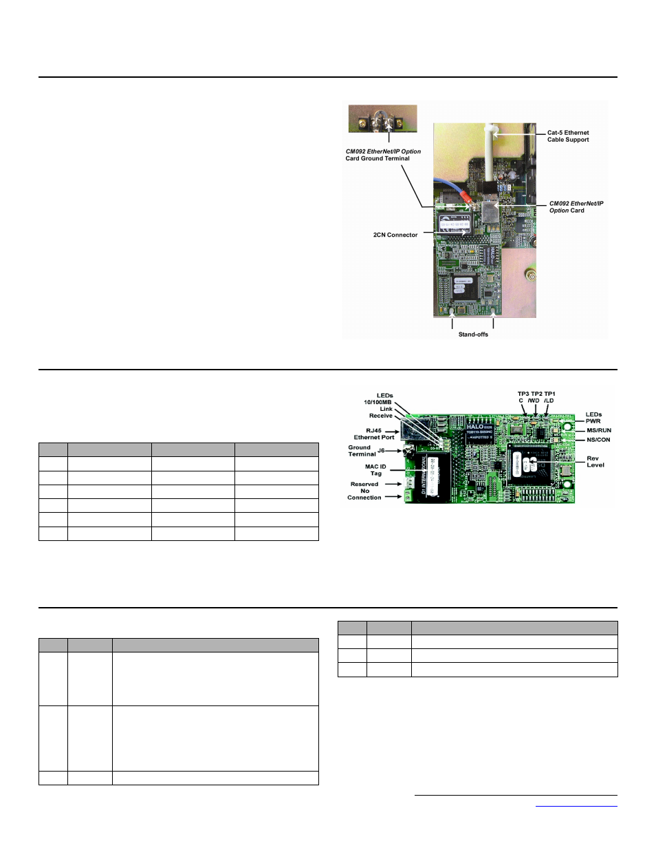
6. Mount the EtherNet/IP Option Card on the G5HHP drive.
a. Attach the CM092 EtherNet/IP Option ground wire to the ground
terminal as shown. Make sure that the terminal is connected to a reliable,
noise free ground.
b. Connect the CM092 EtherNet/IP Option card to the 2CN connector on
the master control board.
c. Secure the Cat-5 Ethernet cable to the support with a tie wrap to provide
strain relief for the connector.
d. Attach the Ethernet cable to the CM092 EtherNet/IP Option card as
shown.
e. Fully engage the stand-offs in the mounting holes on the card.
f.
Route the Ethernet cable away from any power wires within the cabinet.
When outside of the cabinet, run the Ethernet cable in its own conduit.
However, it may be run along with low voltage signals such as feedback
wiring.
7. Diagnostic LED power-up test sequence
A power-up test is performed each time the AC drive is powered up after the
initial boot-up sequence. The initial boot-up sequence may take several
seconds. When this sequence is complete, the LEDs will assume their normal
conditions.
The EtherNet/IP Option Card is successfully initialized after the LEDs have
completed the above sequence.
The EtherNet/IP Option Card LED status after the power-up sequence is
described below. Please wait for at least five seconds for the loading process to
complete before verifying the status of the LEDs.
Successful Initialization:
The EtherNet/IP Option Card hardware is installed and operating correctly with
the LEDs in the states shown in bold text in step 8 per the "LED Descriptions"
table. The LINK LED represents the status of the physical connection to the
network and is not indicative of any card state.
8. LED descriptions
Seq
MS/RUN
NS/CON
Time
1
GREEN
OFF
250ms
2
RED
OFF
250ms
3
GREEN
OFF
250ms
4
GREEN
GREEN
250ms
5
GREEN
RED
250ms
6
GREEN
OFF
LED
Label
Description
D1
MS/RUN
GREEN – Card Functioning Normally
GREEN BLINK – Standby/Initializing (500ms cycle)
RED BLINK – Minor Fault (500ms cycle)
RED – Major Fault
GREEN/RED BLINK – Module Test (500ms cycle)
D2
NS/CON
GREEN – Connected
GREEN BLINK – Waiting for Connections
(500ms cycle)
RED BLINK – Connection Timeout (500ms cycle)
RED – Duplicate IP Address
GREEN/RED BLINK – Network Test (500ms cycle)
D3
10/100
GREEN – 100Mbs Connection Speed
D4
LINK
GREEN – Link Established
D5
Rx
GREEN – Message Being Received
D8
PWR
GREEN - Appropriate Power Supplied to Card
LED
Label
Description