Yaskawa F7 to L1000A User Manual
Page 21
(Header Title) Application Note
Doc#: PL.L1000A.01 Copyright Yaskawa Electric America, Inc.
©2010 www.yaskawa.com September 9, 2010 21 of 57
Subject: Transition Guide
Product: L1000A
Document: PL.L1000A.01
Title: Product Transition Guide – F7 to L1000A
Product Transition Guide – F7 to L1000A
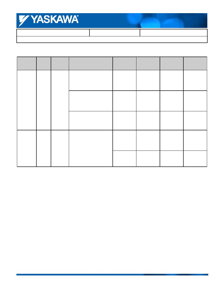
Control Circuit Terminal Size and Gauges
Power
Supply
Model
Capacity
Terminal Signal
Terminal Screw
Tightening
Torque
(N・M)
Possible
Gauges
(mm
2
)
Recommended
Gauges (mm
2
)
FM, AC, AM, P1, P2, PC,
SC, A1, A2, A3, +V, -V,
S1, S2, S3, S4, S5, S6, S7,
S8,
MA, MB, MC, M1, M2
M3.5
0.8 to 1.0
0.5 to 2.0
0.75
MP, RP, R+, R-, S+, S-, IG
M2
Phoenix
Type
0.5 to 0.6
Stranded wire
0.14 to 1.5
single
conductor
0.14 to 2.5
0.75
200 V Class
400 V Class
F7
All
capacities
E (G)
M3.5
0.8 to 1.0
0.5 to 2.0
1.25
M2
0.22 to 0.25
Stranded wire
0.25 to 1.0
single
conductor
0.25 to 1.5
0.75
200 V Class
400 V Class
L1000A
All
capacities
FM, AC, AM, P1, P2, PC,
SC, A1, A2, +V, -V,
S1, S2, S3, S4, S5, S6, S7,
S8,
MA, MB, MC, M1,M2, M3,
M4, M5, M6
H1, H2, HC, DM+, DM-
IG, R+, R-, S+, S-,
E(G)
M2
Phoenix
Type
0.22 to 0.25
0.25 to 0.5
0.5