Yaskawa F7 to L1000A User Manual
Page 43
(Header Title) Application Note
Doc#: PL.L1000A.01 Copyright Yaskawa Electric America, Inc.
©2010 www.yaskawa.com September 9, 2010 43 of 57
Subject: Transition Guide
Product: L1000A
Document: PL.L1000A.01
Title: Product Transition Guide – F7 to L1000A
Product Transition Guide – F7 to L1000A
F7
L1000A
Parameter Name
Parameter
Default
Setting
Record
Parameter
Default
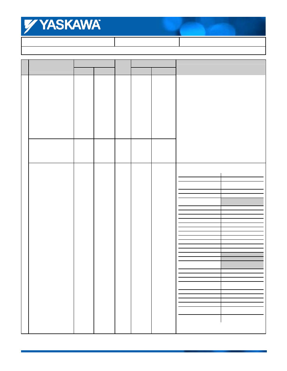
Comments:
Gray shading indicates default setting.
Terminal M3 and M4 Function
Selection
H2-02 1 H2-02 51
Terminal M5 and M6 Function
Selection
H2-03 2 H2-03 6
Digi
tal Outp
ut
s
Terminal P1 Function
Selection
─
─
H2-04 37
F7 L1000A
H2-01 to H2-03
H2-01 to H2-05
19: Torque detection 2
(N.C.)
─
1A: Reverse run
1A: During Down Direction
1B: During baseblock 2
(N.C.)
F: Not Used
1C: Motor selection
─
1D: Regen during run
─
1E: Fault restart
1E: Fault restart
1F: Motor overload alarm
1F: Motor overload alarm
20: Drive overheat alarm
20: Drive overheat alarm
─
2F: Maintenance timer
30: During torque limit
30: During torque limit
31: During speed limit
─
32: Speed limit active
─
33: Zero servo complete
33: Within Position Lock
36: Frequency detection 5
─
37: During run 2
37: During frequency output
─
50: Brake Control
─
51: Output Contactor
Control
─
52: Door Zone Reached
─
53: Not Zero Speed
─
54: Light Load Direction
─
55: Light Load Direction
Detection Status
─
56: Cooling Fan Status
─
57: Input Phase Loss
─
58: Safe Disable Status
3D: Cooling fan malfunction
─
─
61: Rotor detection
complete
─
100-161: 0 to 61 with
Inverse Output