Yaskawa F7 to L1000A User Manual
Page 47
(Header Title) Application Note
Doc#: PL.L1000A.01 Copyright Yaskawa Electric America, Inc.
©2010 www.yaskawa.com September 9, 2010 47 of 57
Subject: Transition Guide
Product: L1000A
Document: PL.L1000A.01
Title: Product Transition Guide – F7 to L1000A
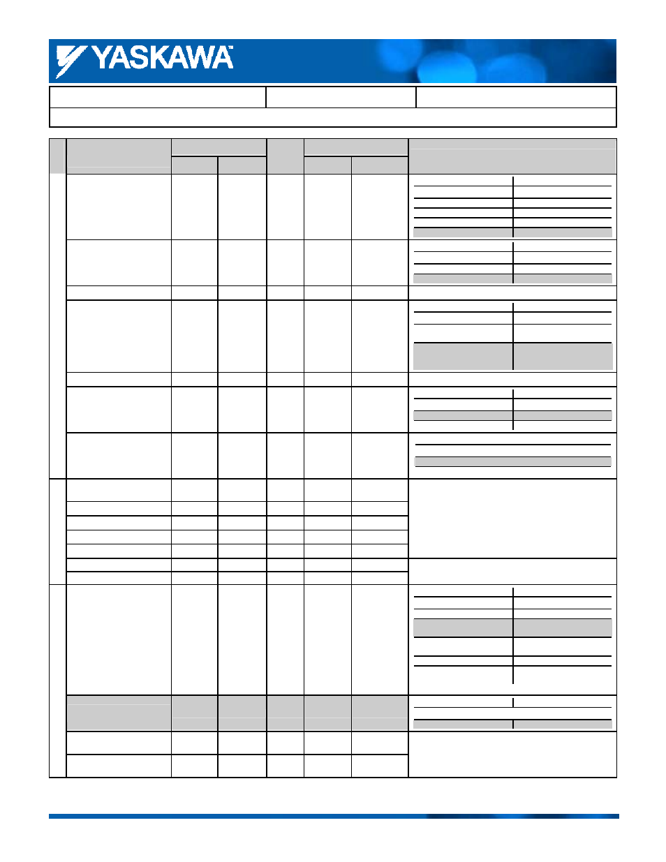
Product Transition Guide – F7 to L1000A
F7
L1000A
Parameter Name
Parameter
Default
Setting
Record
Parameter
Default
Comments:
Gray shading indicates default setting.
Stopping Method After
Communication Error
H5-04 3 H5-04 3
F7 L1000A
H5-04 H5-04
0: Ramp to stop
0: Ramp to stop
1: Coast to stop
1: Coast to stop
2: Fast Stop
2: Fast Stop
3: Continue operation
3: Continue operation
Communication Error
Detection Selection
H5-05 1 H5-05 1
F7 L1000A
H5-05 H5-05
0: Disabled
0: Disabled
1: Enabled
1: Enabled
Send Wait Time
H5-06
5ms
H5-06
5ms
RTS Control Selection
H5-07
1
H5-07
1
F7 L1000A
H5-07 H5-07
0: Disabled
(RTS always on)
0: Disabled
(RTS always on)
1: Enabled
(RTS enabled during send
only)
1: Enabled
(RTS enabled during send
only)
CE Detection Time
─
─
H5-09
2.0
s
Unit Selection for MEMOBUS
Register 0025H
H5-10 0 H5-10 0
F7 L1000A
H5-10 H5-10
0: 0.1 V units
0: 0.1 V units
1: 1 V units
1: 1 V units
MEMOBU
S C
ommunic
at
ion
Communications ENTER
Function Selection
─
─
H5-11 0
L1000A
H5-11
0: Enter Cmd Req.
1: Enter Cmd Not Req.
Pulse Train Input Function
Selection
H6-01 0 ─
─
Pulse Train Input Scaling
H6-02
1440 Hz
─
─
Pulse Train Input Gain
H6-03
100.0%
─
─
Pulse Train Input Bias
H6-04
0.0%
─
─
Pulse Train Input Filter Time
H6-05
0.10 s
─
─
No corresponding parameter in L1000A.
Pulse Train Monitor Selection
H6-06
2
─
─
No corresponding parameter in L1000A.
P
ul
se T
ra
in I/
O
Pulse Train Monitor Scaling
H6-07
1440 Hz
─
─
Motor Overload Protection
Selection
L1-01 1 L1-01 1
*
F7 L1000A
L1-01 L1-01
0: Disabled
0: Disabled
1: General-purpose motor
protection
1: General-purpose motor
protection
2: Drive-dedicated motor
protection
2: Drive-dedicated motor
protection
3: Vector motor protection 3: Vector motor protection
─
5: PM motor protection
(constant torque)
*Determined by the control mode selected.
Motor Overload Protection
Time
L1-02
8.0min
L1-02
1.0 min.
F7 L1000A
Setting Range
0.1 to 20.0 min
0.1 to 5.0 min
Motor Overheat Alarm
Operation Selection
L1-03 3 ─
─
Motor Protection
Function
Motor Overheat Fault
Operation Selection
L1-04 1 ─
─
No corresponding parameter in L1000A.