Yaskawa F7 to L1000A User Manual
Page 54
(Header Title) Application Note
Doc#: PL.L1000A.01 Copyright Yaskawa Electric America, Inc.
©2010 www.yaskawa.com September 9, 2010 54 of 57
Subject: Transition Guide
Product: L1000A
Document: PL.L1000A.01
Title: Product Transition Guide – F7 to L1000A
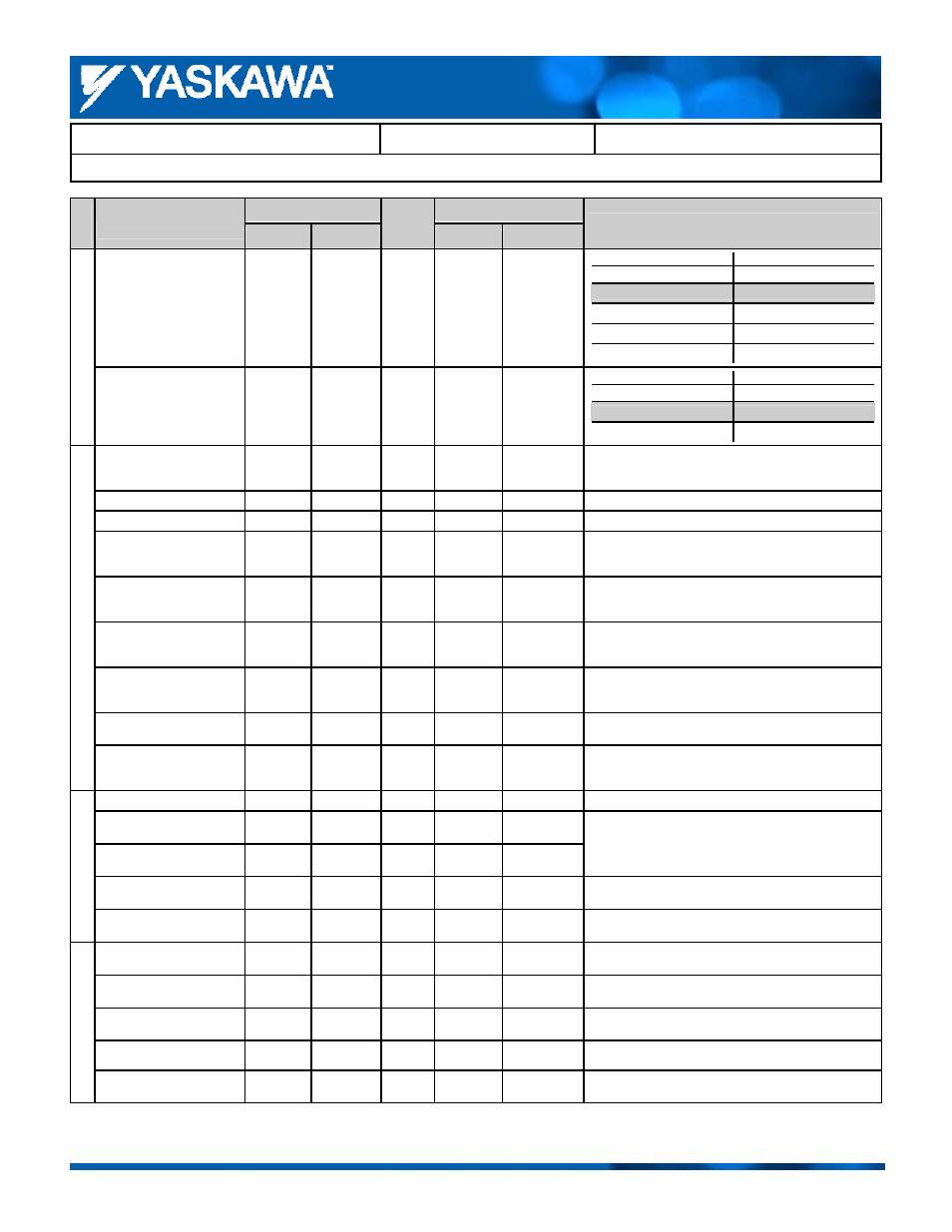
Product Transition Guide – F7 to L1000A
F7
L1000A
Parameter Name
Parameter
Default
Setting
Record
Parameter
Default
Comments:
Gray shading indicates default setting.
Copy Function Selection
o3-01
0
o3-01
0
F7 L1000A
o3-01 o3-01
0: Waiting
0: Waiting
1: READ
1: Read LCD operation
2: COPY
2: Write to the drive
3: VERIFY
3: Verify
C
opy
F
unc
tio
n
Read Permitted Selection
o3-02
0
o3-02
0
F7 L1000A
o3-02 o3-02
0: Read prohibited
0: Read prohibited
1: Read allowed
1: Read allowed
Zero Speed Level at Stop
─
─
S1-01* *
Determined by the control method.
Determines the speed to begin applying DC Injection (or
Position Lock) when the drive is ramping to a stop.
DC Injection Current at Start
─
─
S1-02
50.0
%
─
DC Injection Current at Stop
─
─
S1-03
50.0
%
─
DC Injection/Position Lock
Time at Start
─
─
S1-04
0.40
s
In CLV and CLV/PM, S1-04 determines how long Position
Lock should be performed. A setting of 0.00 disables this
function.
DC Injection/Position Lock
Time at Stop
─
─
S1-05
0.60
s
In CLV and CLV/PM, S1-05 determines how long Position
Lock should be performed. A setting of 0.00 disables this
function.
Brake Release Delay Time
─
─
S1-06
0.20
s
Determines the delay time between the start of Position
Lock and setting the brake control command in order to
release the brake.
Brake Close Delay Time
─
─
S1-07
0.10
s
Determines the delay time between reaching Zero Speed
(S1-01) and resetting the brake control command in order to
apply the brake.
Run Command Delay Time
─
─
S1-10
0.10
s
Sets the delay time after the Up/Down command is entered
until the internal run command is set.
Brake
Seque
nce
Output Contactor Open Delay
Time
─
─
S1-11
0.10
s
Determines the delay time between shutting off the output
of the drive and resetting the contactor control command to
release the motor contactor.
Motor Rated Speed
─
─
S2-01
1380 rpm
Sets the motor rated speed.
Slip Compensation Gain in
Motoring Mode
─
─
S2-02*
0.7
Slip Compensation Gain in
Regenerative Mode
─
─
S2-03*
1.0
*Slip compensation for leveling speed can be set separately
for motoring and regenerative states. This can help
improve the accuracy of leveling.
Slip Compensation Torque
Detection Delay Time
─
─
S2-05
1000
ms
─
Slip Compen
sation for
Eleva
tor
s
Slip Compensation Torque
Detection Filter Time Constant
─
─
S2-06
500
ms
─
Position Lock Gain at Start 1
─
─
S3-01 5
Sets gain levels 1 and 2 for Position Lock at start to avoid
rollback.
Position Lock Gain at Start 2
(Anti Rollback Gain)
─
─
S3-02
0.00
─
Position Lock Gain at Stop
─
─
S3-03 5
Sets the Position Lock gain at stop to keep the car in
position until the brake has been applied entirely.
Position Lock Bandwidth
─
─
S3-04 10
─
Star
t/S
top
Op
tim
iz
ation
Starting Torque
Compensation Increase Time
─
─
S3-10
500
ms
─