Yaskawa F7 to L1000A User Manual
Page 34
(Header Title) Application Note
Doc#: PL.L1000A.01 Copyright Yaskawa Electric America, Inc.
©2010 www.yaskawa.com September 9, 2010 34 of 57
Subject: Transition Guide
Product: L1000A
Document: PL.L1000A.01
Title: Product Transition Guide – F7 to L1000A
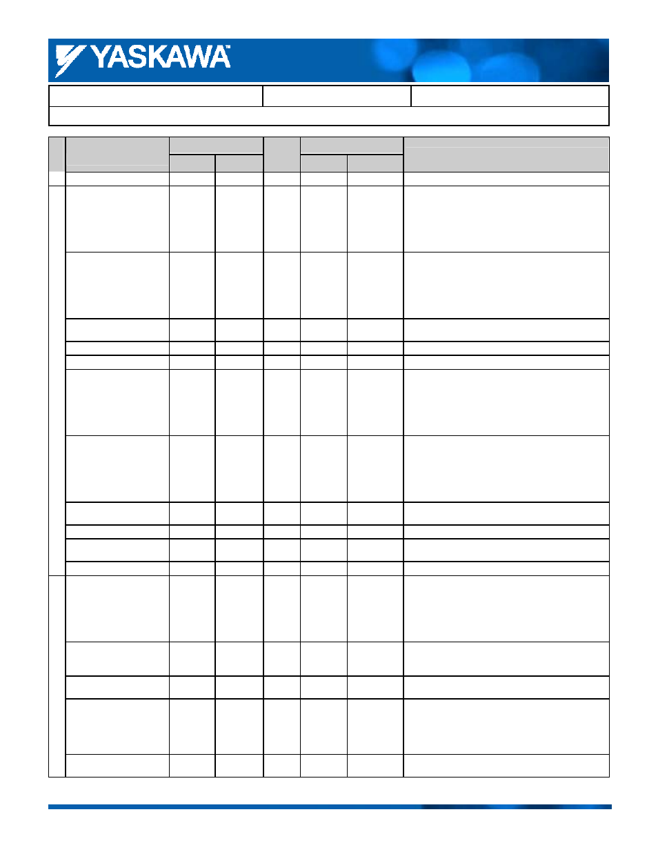
Product Transition Guide – F7 to L1000A
F7
L1000A
Parameter Name
Parameter
Default
Setting
Record
Parameter
Default
Comments:
Gray shading indicates default setting.
Base Voltage
E1-13
0.0 V
E1-13
0.0 V
─
Motor Rated Current
E2-01
*
E2-01
*
*Determined by drive capacity.
Motor Rated Slip
E2-02
*
E2-02
*
*Determined by drive capacity.
Motor De-Coupled Load
Current
E2-03
*
E2-03
*
*Determined by drive capacity.
Motor Poles Count
E2-04
4 poles
E2-04
4 poles
Motor Line-to-Line Resistance
E2-05
*
E2-05
*
*Determined by drive capacity.
Motor Leakage Inductance
E2-06
*
E2-06
*
*Determined by drive capacity.
Motor Iron Core Saturation
Co-Efficient 1
E2-07 0.50 E2-07 0.50
─
Motor Iron Core Saturation
Co-Efficient 2
E2-08 0.75 E2-08 0.75
─
Motor Mechanical Loss
E2-09
0.0%
E2-09
0.0%
─
Motor Iron Loss for Torque
Compensation
E2-10
*
E2-10
*
*Determined by drive capacity.
Motor Parameters
Motor Rated Output
E2-11
*
E2-11
*
*Determined by drive capacity.
Motor 2 Control Method
Selection
E3-01
0
E3-01
*
*Determined by the control mode selected.
Motor 2 Max Output
Frequency
E3-02 60.0
Hz
*
E3-04 60.0
Hz
*
*Determined by the control mode selected.
Motor 2 Max Voltage
E3-03
200.0 V
*
E3-05 200.0
V
*
*Determined by the control mode selected.
Double values for 400 V class drives.
Motor 2 Base Frequency
E3-04
60.0 Hz
*
E3-06 60.0
Hz
*
*Determined by the control mode selected.
Mot
or 2
V/
f
charac
terist
ic
s
Motor 2 Mid. Output
Frequency
E3-05 3.0
Hz
*
E3-07 3.0
Hz
*
*Determined by the control mode selected.