Yaskawa VS-616G5 Modbus Plus Communication Card User Manual
Page 28
Modbus Plus MSTR Function 5-7
NOTE
The Routing 1 serves a dual purpose. The low byte of Routing 1 is used to specify the local
node address. The high byte of Routing 1 is used to specify which Modbus Plus port on the
PLC is to be accessed.
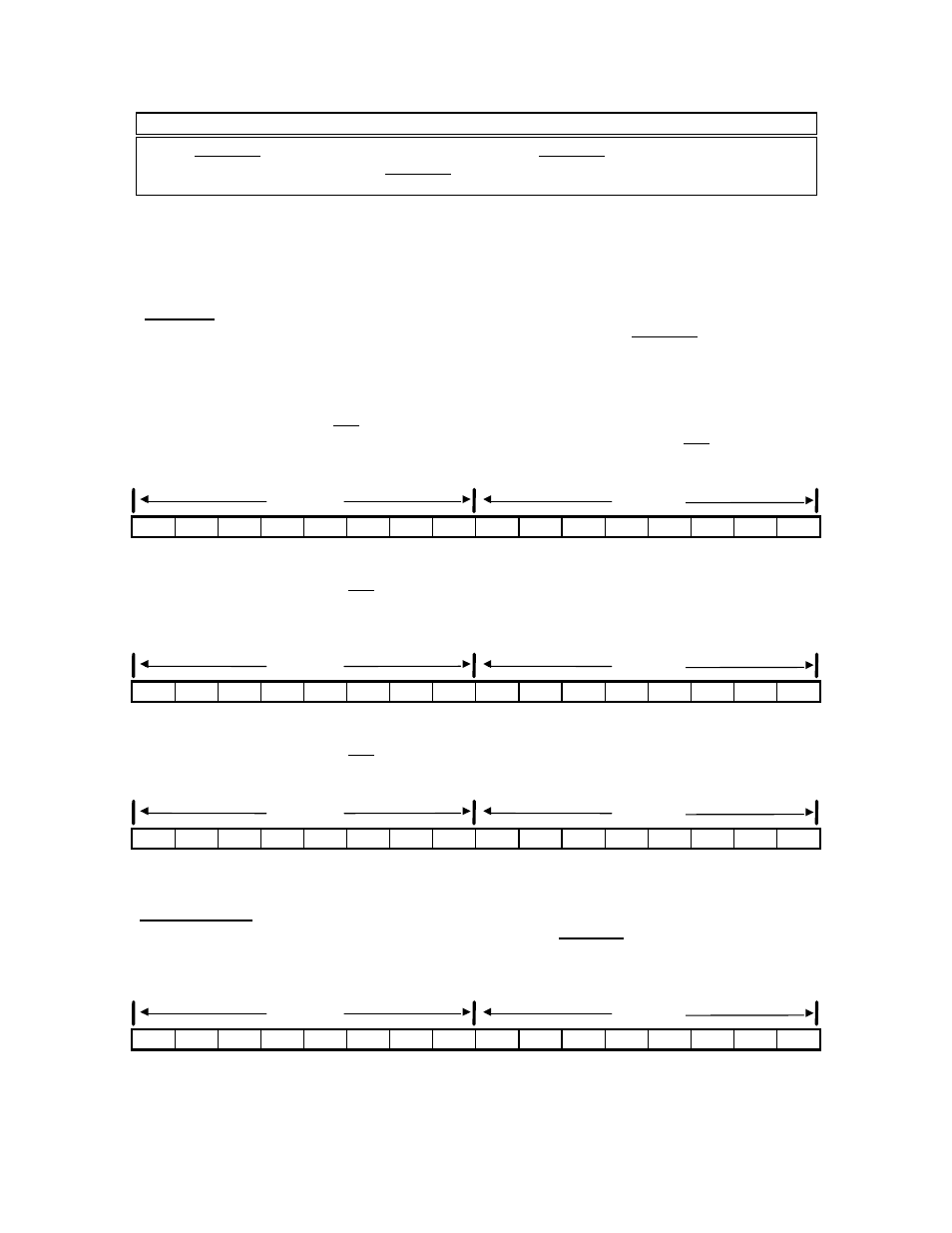
The routing 1 register, used to designate the address of the destination node for a network
transaction. The register display is implemented logically in the 984 PLCs and physically for the
Quantum PLCs:
984 PLCs
For a PLC with only one Modbus Plus port, the value of the high byte of Routing 1 should be set to
zero.
If you are using a PLC with more than one MB+ port the high byte is used to indicate which port
will be accessed.
For an S985-002 board in a 984 chassis mount PLC, a value of 0 in the high byte indicates that
the MSTR instruction is destined for the S985 board set for PLC port #2. For a 984 PLC with
built-in Modbus Plus, a value of 0 in the high byte indicates that the MSTR is destined for the on-
board Modbus Plus port.
0
0
0
0
0
0
0
0
0
0
0
0
1
1
1
1
binary value between 1 and 64
For two S985-002 boards in a 984 chassis mount PLC, a value of 1 in the high byte indicates that
the MSTR instruction is destined for the second S985 board’s assigned buffer space, For an
S985-00 configuration in a PLC with built-in Modbus Plus, a value of 1 in the high byte indicates
that the MSTR is destined for the S985 board set for comm port #2.
0
0
0
0
0
0
0
1
0
0
0
0
1
1
1
1
indicating a second MB+ port
binary value between 1 and 64
For two S985-000 boards in a 984 PLC with built-in Modbus Plus, a value of 2 in the high byte
indicates that the MSTR instruction is destined for the second S985 board’s assigned buffer
space.
0
0
0
0
0
0
1
0
0
0
0
0
1
1
1
1
indicating a second MB+ port
binary value between 1 and 64
Quantum PLCs
To target a Modbus Plus Network Option Module (NOM) in a Quantum PLC backplane as the
destination of an MSTR instruction, the value in the high byte represents the physical slot location
of the NOM. For example, if the NOM resides in slot 7 in the back plane, the high byte of routing
register 1 would look like this:
0
0
0
0
0
0
0
0
0
0
0
0
1
1
1
1
indicating physical location
binary value between 1 and 64
high byte
low byte
high byte
low byte
high byte
low byte
high byte
low byte