Mstr transaction #1 – Yaskawa VS-616G5 Modbus Plus Communication Card User Manual
Page 68
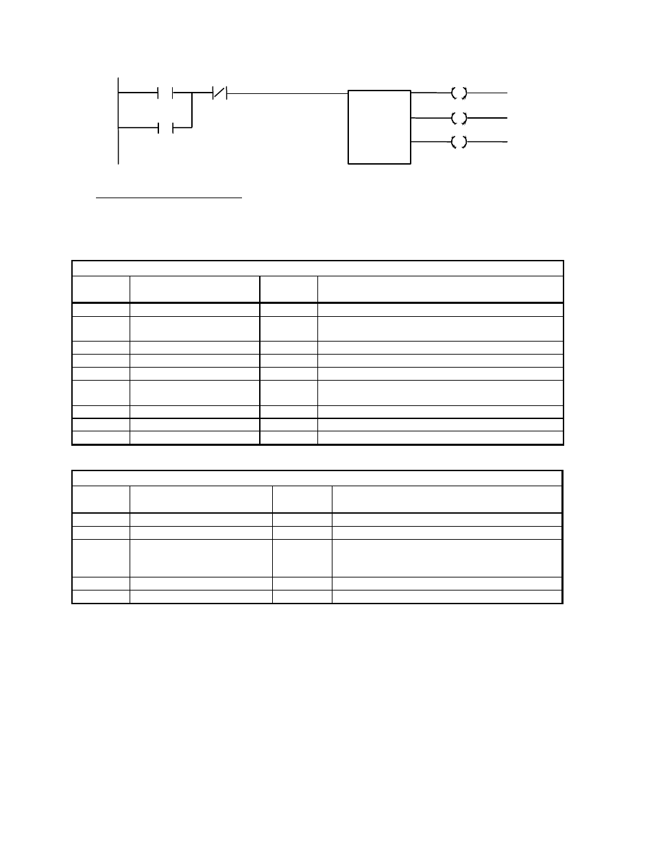
9-24 Examples
00070
00073
00071
00072
00071
00073
MSTR Transaction #1
In this example, the MSTR blocks are executed sequentially. The Control Block and Data Block
registers for the first MSTR must be loaded with the following data before the MSTR block is
executed. This MSTR writes b1-01 through b9-02.
CONTROL BLOCK
Register
Number
Register
Description
Register
Data
Data
Description
40460
Operation Code
0001h
0001h = Write to Multiple Registers
40461
Network Error Code
0000h
The error code returned by Modbus Plus
communications
40462
Number of Registers
0026h
Write to 38 consecutive registers
40463
Data Register Code
0180h
0180h = the start of bx-xx parameters
40464
Routing 1
0003h
Modbus Plus node address of the drive = 0003h
40465
Routing 2
0001h
End of routing path = 0001h (Modbus Plus
requirement)
40466
Routing 3
0000h
This routing register is not used, must be set to 0
40467
Routing 4
0000h
This routing register is not used, must be set to 0
40468
Routing 5
0000h
This routing register is not used, must be set to 0
DATA BLOCK
Register
Number
Register
Description
Register
Data
Data
Description
40470
b1-01
WRITE
Reference Selection
40471
b1-02
WRITE
Operation Method Selection
?
?
?
?
40506
b9-01
WRITE
Zero-Servo Gain
40507
b9-02
WRITE
Zero-Servo Completion Width
40660
40670
MSTR
#0010