Total control-r, Rain dial-r kwikdial, Receiver module installation and setup – Irritrol Climate Logic User Manual
Page 6: Blue wire (up) to pin 1, Cmr-adp
6
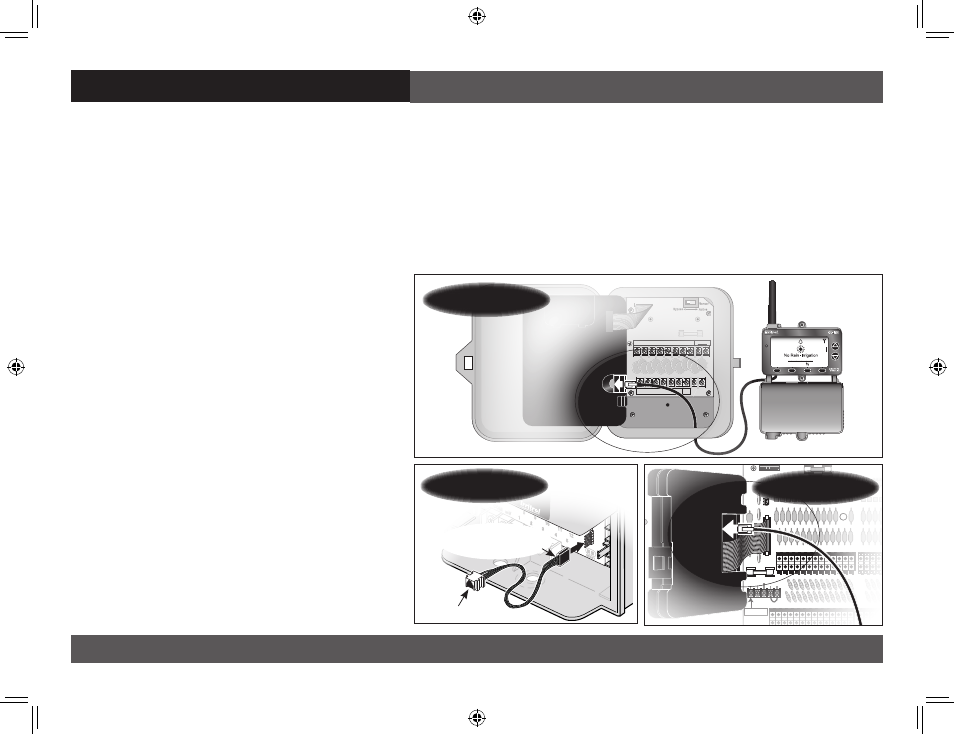
Receiver Module Installation and Setup
Climate Logic System Installation Receiver Module Installation and Setup
Note:
Installation methods must comply with all applicable national and local building codes.
1. Setup controller watering Program A to provide an irrigation baseline for the Climate Logic system.
The station run time, cycle start time(s), and watering day schedule* must be configured for the
hottest/driest conditions expected, without causing over-watering and runoff. Retain all watering
time/day restrictions in the program schedule as required.
Note: By default, Climate Logic modifies the run time of stations assigned only to Program A. To include
Program B, or Programs B and C, see page 13.
*Note: For TMC-212 controller only: Inter-
val day scheduling is not compatible with
Climate Logic. Calendar and Odd/Even
schedules are not affected.
2. Route the connection cable into the con-
troller cabinet. Insert the cable connector
into the controller’s remote control jack.
Note: Use the provided CMR-ADP cable
adapter assembly for KwikDial and MC-E
(Blue) controller applications.
3. Secure the Receiver Module to the wall
next to the controller using the provided
screws or other suitable fasteners.
Note: For indoor application, adhesive-
backed hook and loop tape (not included)
can be used instead of screws.
EARTH
GROUND
MV/
Pump
Sensor
+
-
7
8
9 10 11 12
1
2
3
4
5
6
24 VAC
VC
MENU
_ _ _
F
100%
CLIMATE LOGIC
9:15
a
11/16
MV/
PUMP
1 2 3 4 5 6 7 8 9 10 11 12
MV/
PUMP
24VAC
RAIN
SENSOR
REMOTE
GND
1 2 3 4 5 6 7 8 9 10 11 12
VC/
COM
VC/
COM
13 14 15 16 17 18 19
VC/
COM
37 38 39 40 41 42 43
37 38 39 40 41 42 43
25 26 27 28 29 30 31 32 33 34 35 36
25 26 27 28 29 30 31 32 33 34 35 36
VC/
COM
VC/
COM
VC/
COM
VC/
COM
13 14 15 16 17 18 19
VC/
COM
MV/
PUMP
1 2 3 4 5 6 7 8 9 10 11 12
MV/
PUMP
24VAC
RAIN
SENSOR
REMOTE
GND
1 2 3 4 5 6 7 8 9 10 11 12
VC/
COM
VC/
COM
13 14 15 16 17 18 19
VC/
COM
37 38 39 40 41 42 43
37 38 39 40 41 42 43
25 26 27 28 29 30 31 32 33 34 35 36
25 26 27 28 29 30 31 32 33 34 35 36
VC/
COM
VC/
COM
VC/
COM
VC/
COM
13 14 15 16 17 18 19
VC/
COM
POST
HOT
Total Control-R
CMR-ADP
Blue Wire
(Up) to Pin 1
Rain Dial-R
KwikDial
CL User Guide Final Edit.indd 6
2/11/11 5:19 PM