Epson EB-1460Ui User Manual
Page 40
Installation Guide
39
b
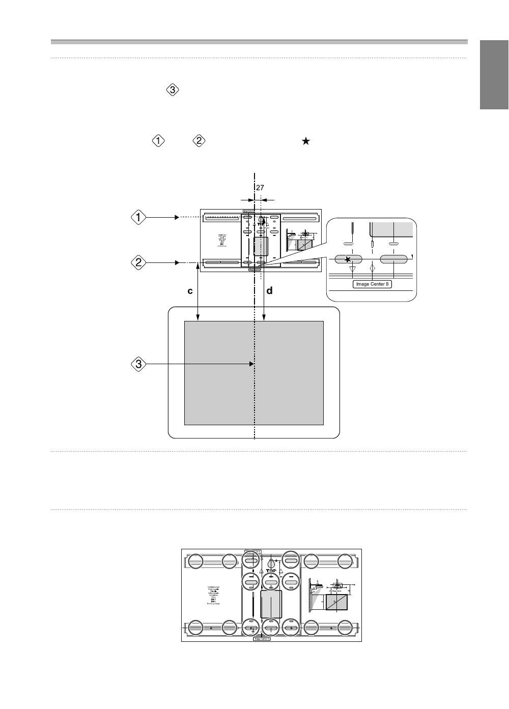
Attach the template sheet to the wall
•
Match the center line (
) checked in step 1 to the Image Center B line on the template sheet.
Confirm where the beams are within the wall, and shift the position left or right as necessary.
(The position can be shifted horizontally left or right from the center line of the projection surface up to a
maximum of 45 mm.)
•
Match the height (
) and (
) checked in step 1 to the
lines on the template sheet.
[Unit: mm]
c
Drive a commercially available M10 screw into the position of the temporary screw hole
for the wall plate
Leave a gap of 6 mm or more between the wall and the screw head.
d
Determine the positions for the mounting holes for the wall plate
From the screw holes shown in the figure below, secure at least four points for optimum balance.