Rose Electronics Xtensys User Manual
Page 12
XTENSYS INSTALLATION AND OPERATIONS MANUAL
6
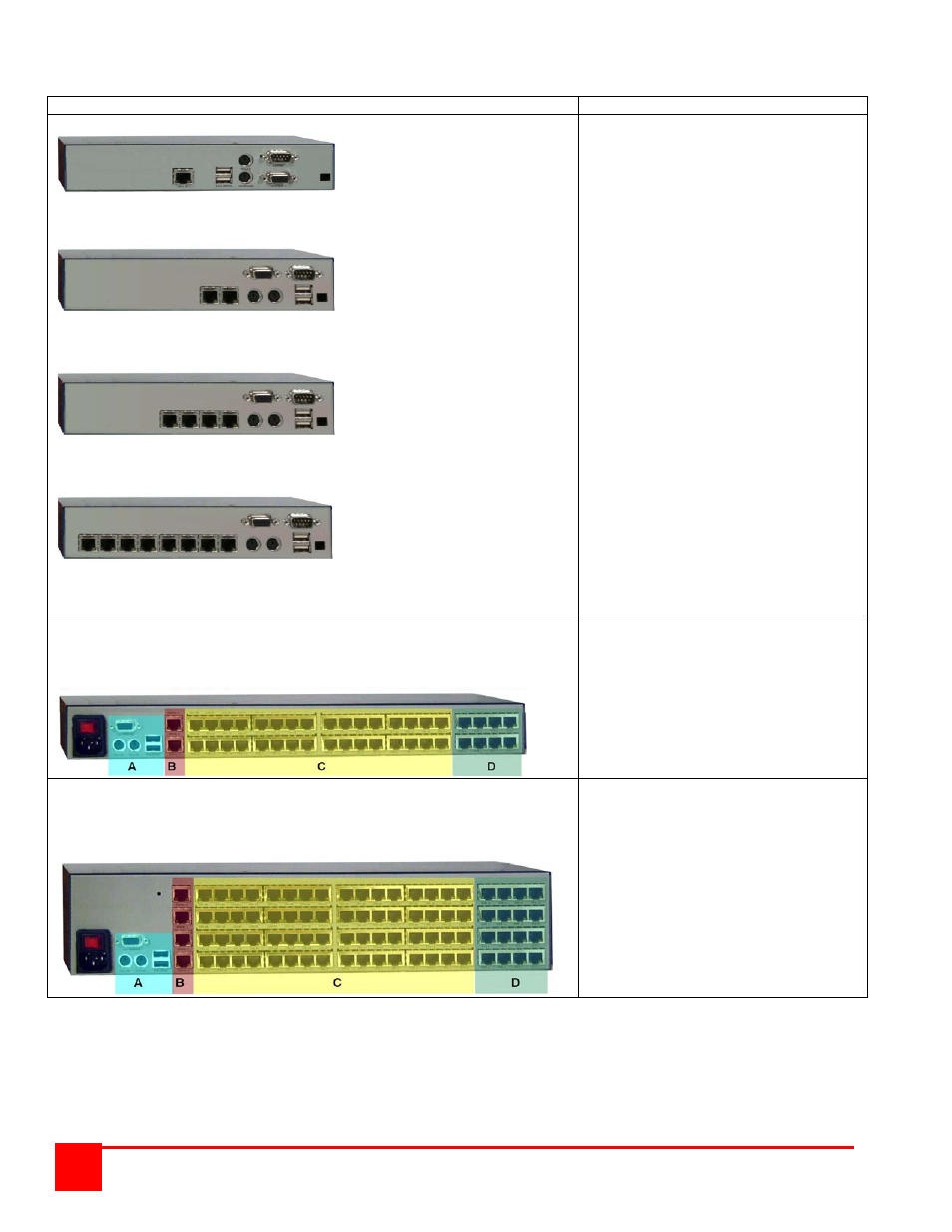
Rear View
Models
Description / Connectors
XTR-11
XTR-12
XTR-14
XTR-18
User Station
XTR-11 (1) RJ45 Link
(2) USB (Kbd/Mouse)
(2) PS/2 (Kbd/Mouse)
(1) HD15F (Video out)
(1) DB9M (Serial)
(1) Power
XTR-12 (2) RJ45 Link
(2) USB (Kbd/Mouse)
(2) PS/2 (Kbd/Mouse)
(1) HD15F (Video out)
(1) DB9M (Serial)
(1) Power
XTR-14 (4) RJ45 Link
(2) USB (Kbd/Mouse)
(2) PS/2 (Kbd/Mouse)
(1) HD15F (Video out)
(1) DB9M (Serial)
(1) Power
XTR-18 (8) RJ45 Link
(2) USB (Kbd/Mouse)
(2) PS/2 (Kbd/Mouse)
(1) HD15F (Video out)
(1) DB9M (Serial)
(1) Power
A = PS/2 – HD15 Local KVM ports B = RJ11 for Flash upgrading
C = RJ45 connectors to Computers D = RJ45 connectors to User station
Switch
The 1U chassis can be configured with:
1. 1 Local KVM input (A)
2. 1 or 2 Serial inputs (B)
3. 4, 8, 16, or 32 CPU connectors (C)
4. 0, 2, 4, or 8 KVM connectors (D)
A = PS/2 – HD15 Local KVM ports B = RJ11 for Flash upgrading
C = RJ45 connectors to Computers D = RJ45 connectors to User station
Switch
The 2U chassis can be configured with:
1. 1 Local KVM input (A)
2. 1, 2, 3 or 4 Serial inputs (B)
3. 8, 16, 32, 48 or 64
CPU connectors (C)
4. 0, 2, 4, 8, or 16
KVM connectors (D)
NOTE: The local KVM connection (A) shares a common video path with the remote KVM connection port #8 (D). It is
recommended that when the local KVM is going to be used, the local user check to assure that KVM port #8
is not in use by a remote user. This can be easily observed by pressing and releasing the left control (Ctrl)
key, then the ESC key, then F2 (Connections). A list of all CPU ports and their status will display (See
Figure 11). Check if KVM station #8 is connected to a computer name. If so notify the remote user on KVM
port #8 that you are going to connect to a CPU port and for them to save their work and disconnect.