Rose Electronics Xtensys User Manual
Page 15
XTENSYS INSTALLATION AND OPERATIONS MANUAL
9
Powering up the system
It is recommended that the system be powered up in the following sequence. This sequence will assure that all the
connected equipment will boot properly.
First – Turn on all monitors (Local KVM monitor and all remote monitors connected to user stations)
Next – Turn on the Xtensys switch. Wait for all indicators to stabilize. This indicates that the internal
diagnostic check is complete
Next – Connect the provided power adapter to the user stations
Next – Connect the power adapter to the power source to apply power to the User Stations
Last – Boot / turn on all connected computers or serial devices.
LED Indicators
CPU,
KVM,
or
Serial
LED
Each RJ45F connector has an amber and green LED located at the bottom right and left of the
connector. When power is first applied, these LED’s will flash, indicating the self test and internal
diagnostic check is being performed. Once these tests are completed, these LED indicators will indicate
the following status or information:
CPU LED’s - All CPU LEDs will cycle during power up. On completion of the diagnostic tests, the
green Led will light if there is a device connected to that CPU port. The amber LED will light and will
flash showing activity at that CPU port
KVM LED’s – The Green LED will light when there is a user station connected to that KVM port and
power is applied to the user station. The amber LED will light and flash showing KVM activity on
that KVM port
ALL KVM and the Serial LED’s (connected or not connected) will laminate dimly.
Configuring the Xtensys Switch
The Xtensys switch must have the CPU ports configured for either a UTP connection or a Serial connection. The
default configuration is UTP. Only the CPU ports that are connected to a serial device have to be configured for
serial functions.
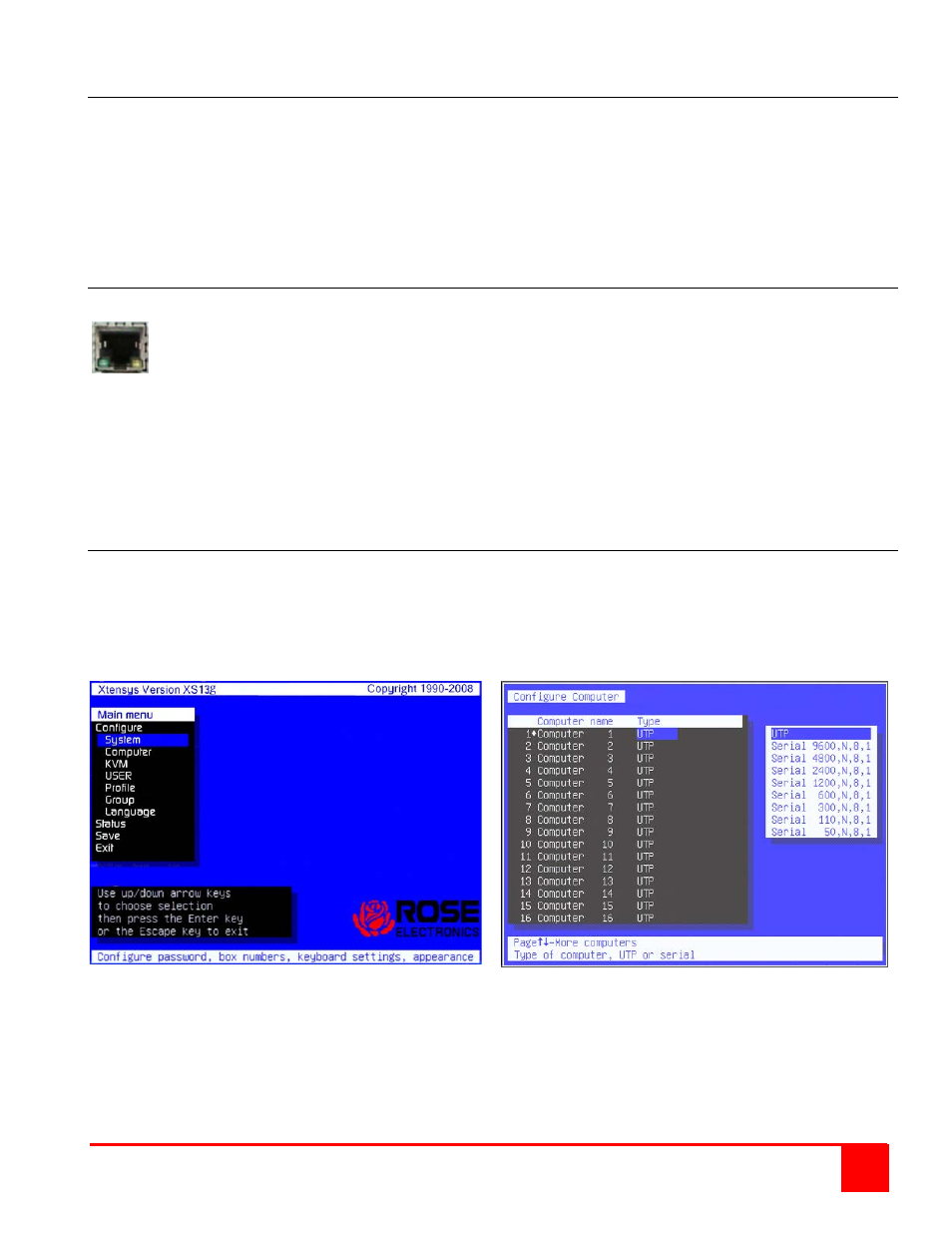
To configure a CPU port for serial functions call up the OSD from the local User Station’s KVM by pressing and
releasing the left control key, they within 2 seconds, press the F12 key. The main OSD menu will display as shown
below.
Use the up / down arrow keys to select Computer and press enter. The “Configure Computer” menu will display.
Select the computer port that will be connected to a serial device then press the right arrow key to tab to the “Type”
field and press enter. A selection box will display listing the configuration options available for the selected computer
port. Select the serial configuration needed and press enter. If other Computer ports need to be configured for serial,
select those computers and configure them in the same manor. When complete, press the “Esc” key to return to the
main menu, select “Save” and press enter. Then exit the OSD menu system by pressing the ESC key. The CPU
ports that were changed from UTP to Serial are now configured for serial functions.
(NOTE: DO NOT PROGRAM CPU PORT #1 FOR SERIAL OPERATION)