Rose Electronics Xtensys User Manual
Page 47
XTENSYS INSTALLATION AND OPERATIONS MANUAL
41
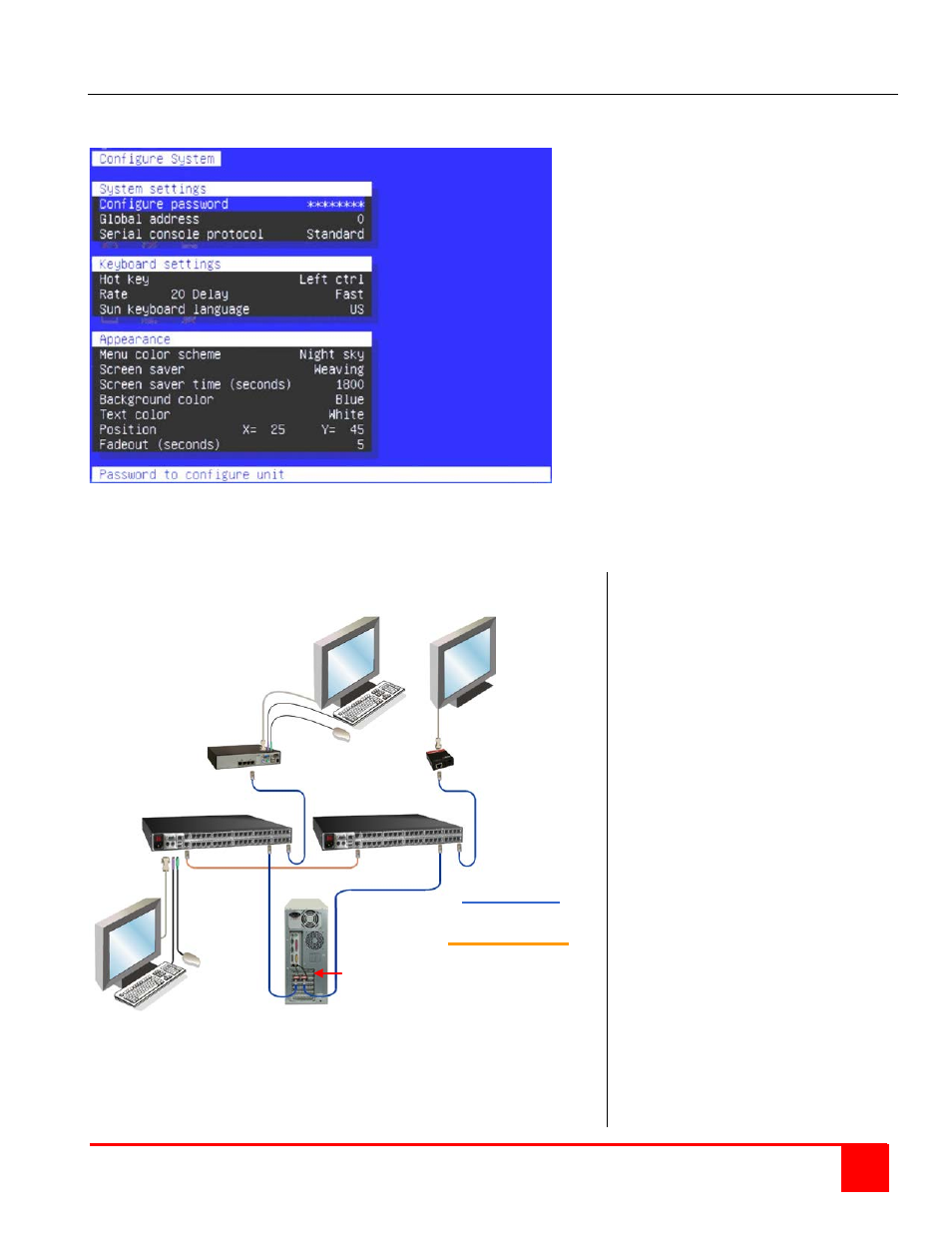
Appendix E. Serial console protocol (Standard, Switch, Event configuration)
The Serial Console Protocol feature allows you to configure the Xtensys switch to perform alternative functions. The
default setting is “Standard”. In this mode all functions and features operate normally.
Setting this protocol to “Switch” configures Xtensys to send port switching commands to the serial port. When a
command is given to the main unit to switch to CPU port #5, this command is also sent to the serial port.
The below example shows how, using a computer with a dual video card can be set-up.
Connect two Xtensys transmitters
to the video ports on the PC.
Connect a CAT5 cable from each
transmitter to the same CPU port
number on the Main and the
Secondary Xtensys unit.
Use a standard crossover cable
to connect the Main unit’s serial
port to the Secondary unit’s serial
port.
Connect a CAT5 cable from KVM
port #1 on the Main unit to a user
station’s CPU port or, if only video
in needed, connect to an Xtensys
receiver.
Connect a CAT5 cable from KVM
port #1 on the Secondary unit to
an Xtensys receiver.
Connect the monitors and/or
keyboard and mouse to the
Receiver, user station, and local
Xtensys port on the Main unit.
Power on all devices
(Power adapter is needed for the
Receivers)
Display the Xtensys OSD on unit
#1 (Press and release Ctrl + F12)
Select system, then select “Serial
Console Protocol” and change
from standard to switch.
Save the configuration changes.
Main Unit Secondary Unit
Two Xtensys Transmitters
(One on each video port)
Xtensys Xtensys Receiver
User Station
or Receiver
CAT5 Cable
Crossover Cable
PC with dual
video output