5 wiring the faulty alarm contact, 6 cabling – PLANET IGS-504HPT User Manual
Page 17
17
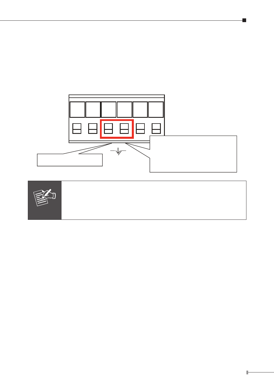
2.1.5 Wiring the Faulty Alarm Contact
The faulty alarm contacts are in the middle of the terminal block connector as
the picture shows below. Inserting the wires, the Industrial Gigabit PoE+ Switch
will detect the fault status of the power failure, or port link failure (available for
managed model) and then forms an open circuit. The following illustration shows
an application example for wiring the faulty alarm contacts.
Faulty Alarm Contacts
The Faulty Alarm Contacts are
energized (CLOSE) for normal
operation and will OPEN when
failure occurs
Fault
1 2 3 4 5 6
Note
1. The wire gauge for the terminal block should be in the range of
12 ~ 24 AWG.
2. Alarm relay circuit accepts up to 30V, max. 3A currents.
2.1.6 Cabling
10/100/1000BASE-T
All 10/100/1000BASE-T ports come with Auto-Negotiation capability. They
automatically support 1000BASE-T, 100BASE-TX and 10BASE-T networks. Users
only need to plug a working network device into one of the 10/100/1000BASE-T
ports, and then turn on the Industrial Gigabit PoE+ Switch. The port will
automatically runs in 10Mbps, 20Mbps, 100Mbps or 200Mbps and 1000Mbps or
2000Mbps after the negotiation with the connected device.
100BASE-FX/1000BASE-SX/LX
The IGS-624HPT Industrial Gigabit PoE+ Switch has two SFP interfaces that
support 100/1000 dual speed mode (optional multi-mode/single-mode 100BASE-
FX/1000BASE-SX/LX SFP module) through DIP switch setting.
Cabling
Each 10/100/1000BASE-T port uses RJ45 sockets -- similar to phone jacks -- for
connection of unshielded twisted-pair cable (UTP). The IEEE 802.3/802.3u/802.3ab