ProSoft Technology MVI46-DFCM User Manual
Page 20
MVI46-DFCM ♦ SLC Platform
Installing and Configuring the Module
DF1 Communication Module
Page 20 of 103
ProSoft Technology, Inc.
October 20, 2008
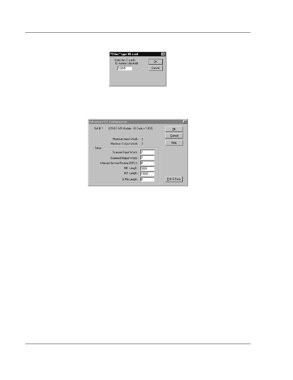
Select the Other module from the list. This action opens the following dialog box.
Enter the module I/O card ID number as 12835, and then click OK. Double-click
the mouse on the module just added to the rack. Fill in the dialog box presented
as shown below:
Click OK to apply these settings to the module. Then, close the I/O Configuration
dialog box.
Next, define the user defined data areas to hold the configuration, port command
lists, status and read and write database areas.
At this point, take the time to fill in the configuration values in the DFCM
configuration data table. Refer to the Module Data section of this document for
information on configuring the module.
The last step in the module setup is to add the ladder logic. If the example ladder
logic is used, adjust the ladder to fit the application. When the ladder example is
not used, copy the example ladder logic to your application and alter as
necessary.
The module is now set up and ready to be used with your application. Insert the
module in the rack and attach the DF1 serial communication cables. Download
the new application to the controller and place the processor in run mode. If all
the configuration parameters are set correctly and the module is attached to a
DF1 network, the module's Application LED (APP LED) should remain off and the
backplane activity LED (BP ACT) should blink very rapidly. Refer to Diagnostics
& Troubleshooting (page 35) if you encounter errors. Attach a computer or
terminal to Debug/Configuration port on the module and look at the status of the
module using the Configuration/Debug Menu in the module. Refer to
Troubleshooting (page 52) for a complete discussion of the use of this feature.