Using the port and parameter definitions, Altiobuf functional description – Altera I/O Buffer (ALTIOBUF) IP Core User Manual
Page 10
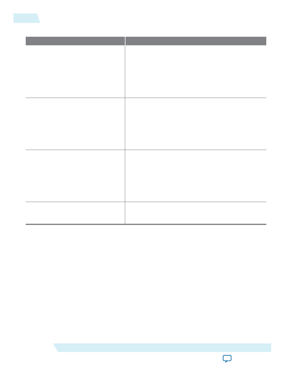
Table 3: ALTIOBUF Parameters: Dynamic Delay Chains Tab
Parameter
Description
Enable input buffer dynamic delay chain If enabled, the input or bidirectional buffer incorporates the
user-driven dynamic delay chain in the IP core; that is, the
IO_CONFIG
and the input delay cell. Additional input ports are
enabled:
io_config_clk
,
io_config_clkena
,
io_config_
update
, and
io_config_datain
.
This option is not available for Cyclone III and Cyclone IV
devices.
Enable output buffer dynamic delay chain
1
If enabled, the output or bidirectional buffer incorporates the
user-driven dynamic delay chain in the IP core; that is, the
IO_CONFIG
and the first output delay cell. Additional input
ports are enabled:
io_config_clk
,
io_config_clkena
,
io_
config_update
, and
io_config_datain
.
This option is not available for Cyclone III and Cyclone IV
devices.
Enable output buffer dynamic delay chain
2
If enabled, the output buffer or bidirectional buffer incorpo‐
rates a user-driven dynamic delay chain in the IP core; that is,
the
IO_CONFIG
and the second output delay cell. Additional
input ports are enabled:
io_config_clk
,
io_config_clkena
,
io_config_update
, and
io_config_datain
.
This option is not available for Cyclone III and Cyclone IV
devices.
Create a ‘clkena’ port
If enabled, there is a port used to control when the configura‐
tion clock is enabled. This option is not available for Cyclone
III and Cyclone IV devices.
Using the Port and Parameter Definitions
Instead of using the parameter editor GUI, you can instantiate the IP core directly in your Verilog HDL,
VHDL, or AHDL code by calling the IP core and setting its parameters as you would any other module,
component, or subdesign.
Related Information
on page 16
ALTIOBUF Functional Description
10
Using the Port and Parameter Definitions
UG-01024
2014.12.15
Altera Corporation
I/O Buffer (ALTIOBUF) IP Core User Guide