Power monitoring, Power monitoring –20 – Altera Signal Integrity Development Kit, Stratix V GX Edition User Manual
Page 40
6–20
Chapter 6: Board Test System
Power Monitoring
Transceiver Signal Integrity Development Kit
July 2012
Altera Corporation
Stratix V GX Edition User Guide
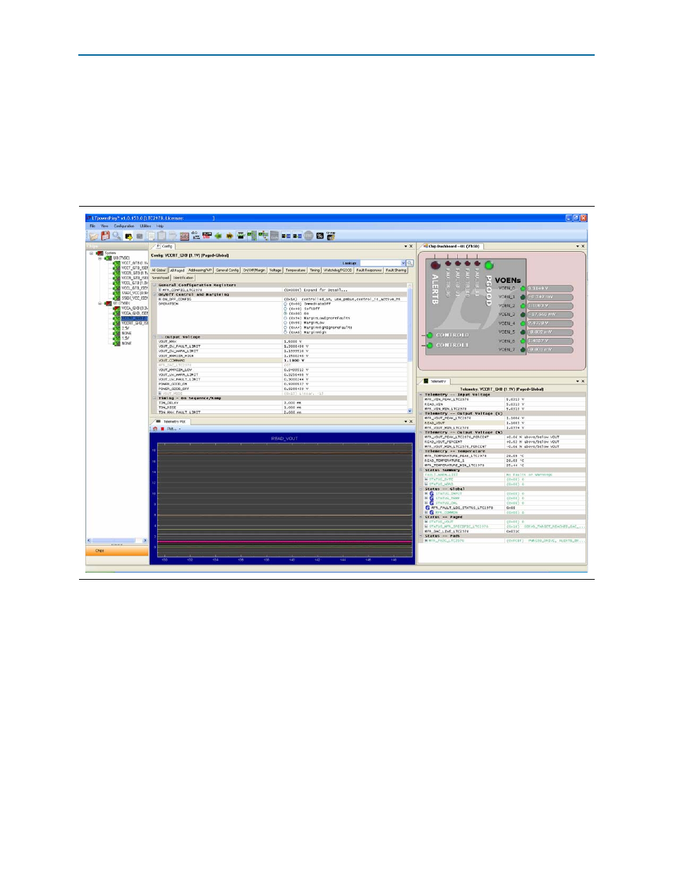
Power Monitoring
To measure and view current power information for the transceiver signal integrity
development board, you need install the free LTpowerPlay™ software, and then
connect your PC and the development board to a Linear Technology DC1613A
USB-to-PMBus Controller. Both the software and the controller interface are available
from the Linear Te
) website.
shows the
LTpowerPlay GUI.
1
The DC1613A USB-to-PMBus controller communicates with the LTC
®
2978 on-board
octal PMBus power supply monitor and controller at the U10/11 board reference. For
more information on the LTC2978, refer to the
c
The LTC 2978 power monitor devices installed on this board are programmed with a
project file that sets up each voltage rail according to a sequence. Each voltage rail will
adjust to its voltage level to within tolerance. However, if the development board is
powered off and powered on again with SW2 in the open position, the voltage rails
VCCRT_GXB and VCCA_GXB will not come up to the proper levels unless SW2-1
and SW2-2 are set to the default closed position at power up. For SW2 switch settings,
refer to the default settings in
Figure 6–9. LTpowerPlay