Setup elements, Board settings dip switch, Setup elements –17 – Altera Cyclone V SoC Development Board User Manual
Page 25: Board settings dip switch –17
Chapter 2: Board Components
2–17
Setup Elements
November 2013
Altera Corporation
Cyclone V SoC Development Board
Reference Manual
Setup Elements
The development board includes several different kinds of setup elements. This
section describes the following setup elements:
■
Board settings DIP switch
■
JTAG chain control DIP switch
■
FPGA configuration mode DIP switch
■
HPS jumpers
■
CPU reset push button
■
MAX V reset push button
■
Program configuration push button
■
Program select push button
f
For more information about the default settings of the DIP switches, refer to the
Board Settings DIP Switch
The board settings DIP switch (SW2) controls various features specific to the board
and the MAX V CPLD 5M2210 System Controller logic design.
Table 2–8
lists the
switch controls and descriptions.
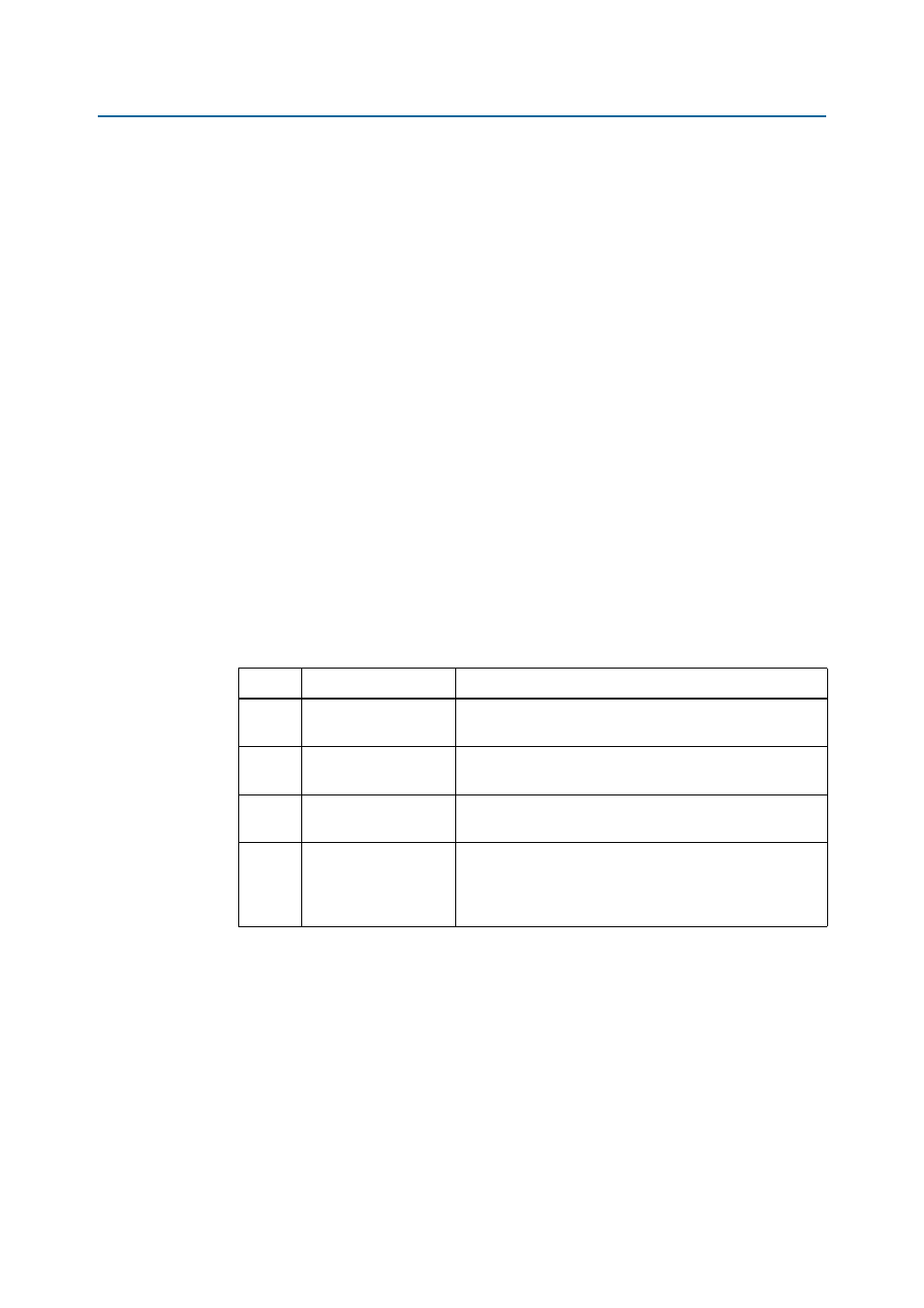
Table 2–8. Board Settings DIP Switch Controls
Switch
Schematic Signal Name
Description
1
CLK125A_EN
ON: Select programmable oscillator clock
OFF: Select SMA input clock
2
Si570_EN
ON: Disable on-board oscillator
OFF: Enable on-board oscillator
3
FACTORY_LOAD
ON: Load the factory design from flash at power up.
OFF: Disable the PFL and do not configure from flash.
4
SECURITY_MODE
ON: Embedded USB-Blaster II sends FACTORY command at
power up.
OFF: Embedded USB-Blaster II will not send FACTORY
command at power up.