Power and connect the unit – CIRCUTOR CIReQ User Manual
Page 19
_______________________________________________________
_________________________________________________________________________________________________________
CIR-eQ User’s Manual
19 of 36
Is obligatory follow this installation procedure:
1. Insert SD card.
2. Insert B connector, voltage references.
3. Power the analyzer.
4. Check the voltage phase inversion.
5. Start the recording process.
After inserting the SD card in the analyzer's slot, connect it to start measuring and taking
the readings of the installation's electrical parameters. The connection process is
explained in detail in the following points.
6.3.1.- POWER AND CONNECT THE UNIT
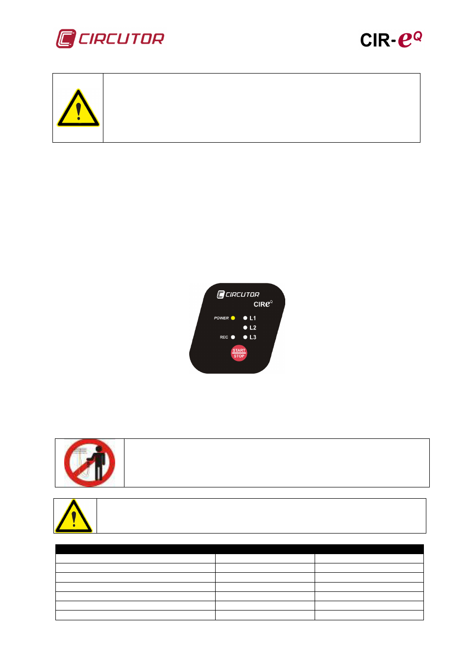
Insert connector “B”, corresponding to the voltages references of CIR-eQ before
powering the unit. The analyzer is powered with the brown and green auxiliary power
supply wires. When you connect the auxiliary power supply cables, the unit will do the
boot sequence recognized by the sequential ignition of LED L1, L2, L3 and POWER
LED.
Once the boot sequence is done the device indicates that is powered by the LED
POWER.
After powering the unit, connect the phase voltages. If you need to power the
measurement's analyzer, you can connect the reference voltages to power it.
To power and connect the analyzer correctly, respect the phase sequence, as shown on
the table.
Do not handle when voltage references are
connected.
The colours of voltage phases can change according to the colour scheme
selected in the device code. The following table lists the references for each
phase of the different colours.
PHASE
EUROPEAN
RYBLB
Phase reference
Wire colour
Wire colour
(L 1) PHASE 1
BLACK
RED
(L 2) PHASE 2
RED
YELLOW
(L 3) PHASE 3
YELLOW
BLUE
(N) NEUTRAL
BLUE
BLACK
Auxiliary supply
BROWN
BROWN
Auxiliary supply
GREEN
GREEN