Three-phase connection diagram (4 wires), Verification of connections, Faulty connection – CIRCUTOR CIReQ User Manual
Page 21
_______________________________________________________
_________________________________________________________________________________________________________
CIR-eQ User’s Manual
21 of 36
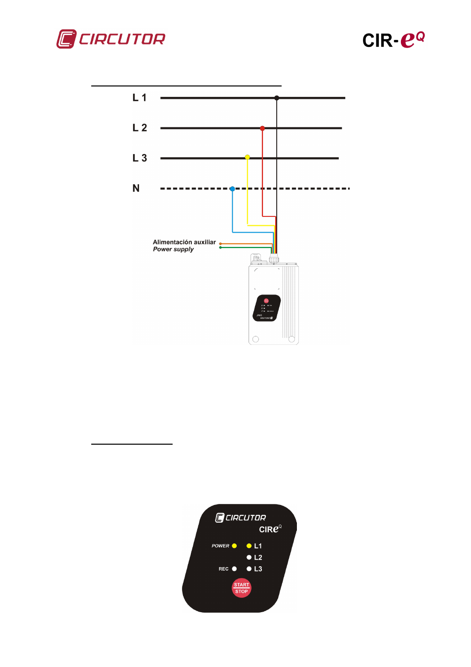
6.3.1.3.- Three-phase connection diagram (4 wires)
6.3.2.- VERIFICATION OF CONNECTIONS
The analyzer will start the connection verification process after power it. This process is
carried out by the unit continuously, regardless of whether it is recording data or not.
We must highlight that the analyzer will indicate faulty connections with the L1, L2 or L3
LED and the indication is realized by the lighted LED (correct connection) or blinking
(incorrect connection).
6.3.2.1.-
The analyzer indicates a faulty connection for voltage sequence error blinking the L1, L2
or L3 LED.
Faulty connection
The figure shows an example of how the CIR-eQ unit indicates the faulty connection of
voltages in phases L2 and L3. In this case, exchange the voltage connections, i.e., L2
and L3.