Installation – Pinnacle Systems STTS User Manual
Page 10
4
INSTALLATION
WARNING: The entire machine safety system
must be tested at the start of every shift.
Machine testing should include: (1) proper
machine operation and stopping capability; and
(2) verification of proper installation and
settings of all point of operation guards and
devices before the operation is released for
production.
The STTS mat system has been designed to
promote individual mat "homerun" wiring back
to the mat controller. This is suggested for
easing installation and diagnostics for
maintenance troubleshooting. This will also eliminate cumbersome "daisy chain" wiring practices of mat
systems. It also eliminates numerous wiring connection points buried under the perimeter trim, which are
time intensive to troubleshoot.
INSTALLATION
1) Sweep the floor area where the safety mat is to be installed. The floor should be flat and free of
foreign material.
2) Locate the safety mat in the desired location. For future reference,
install the mat with the label side
up.
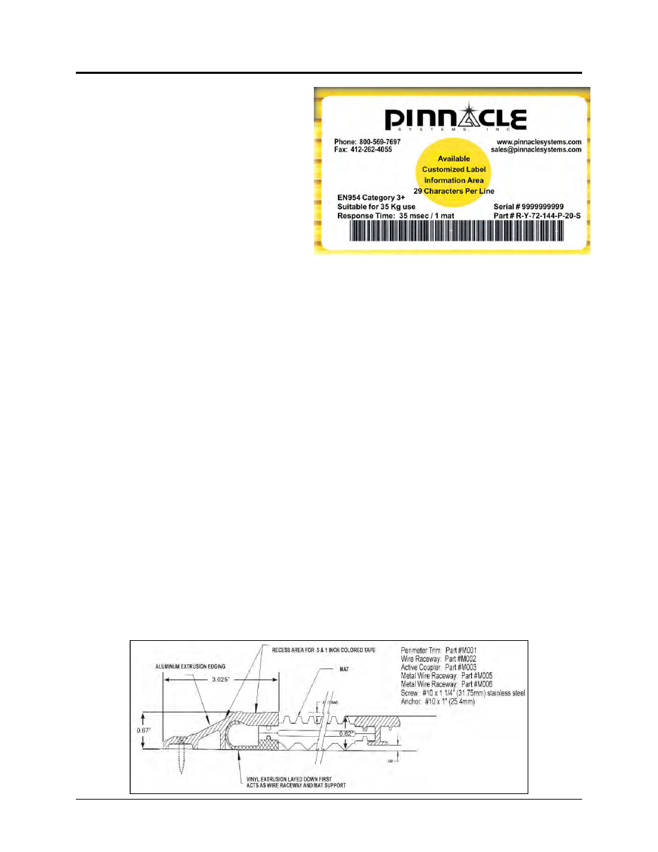
3) Slide the black wire raceway component under the mat edge (Part #M002). Refer to the graphic
below for proper component positioning. NOTE: The wire raceway component must be installed
whenever the surface perimeter trim component is used.
4) Route the wire/plug assembly on the raceway toward the mat controller location.
5) Lay the aluminum perimeter trim piece around the mat assembly. Determine where the mat wiring
will exit the trim and notch the trim and wire raceway for the wire to exit the assembly.
6) If surface metal raceway is used to route the wiring (Part #M005 or M006) from the mat assembly
across the floor toward the mat controller, it should be aligned with the notch in the perimeter trim and
anchored to the floor. Route wires accordingly and snap cover plate over the wires.
7) Slide the perimeter trim over the wire raceway component and align over the mat edge per Figure 1.
Drill the perimeter trim and floor for securing the perimeter trim to the floor with anchoring screws and
floor anchors.
8) If a multiple mat assembly is to be installed, use the aluminum active coupler component (Part
#M003) to connect mats end-to-end or side-to-side. Refer to graphic below.
Cross Section View of Mat Assembly Active Edging