Accessible connections (din-rail controller) – Pinnacle Systems STTS User Manual
Page 16
10
ACCESSIBLE CONNECTIONS (Din-Rail controller)
Internal:
J1
Diagnostics display plug (used by remote status display option)
The Plug is located under the top cover on the left side of the controller
External:
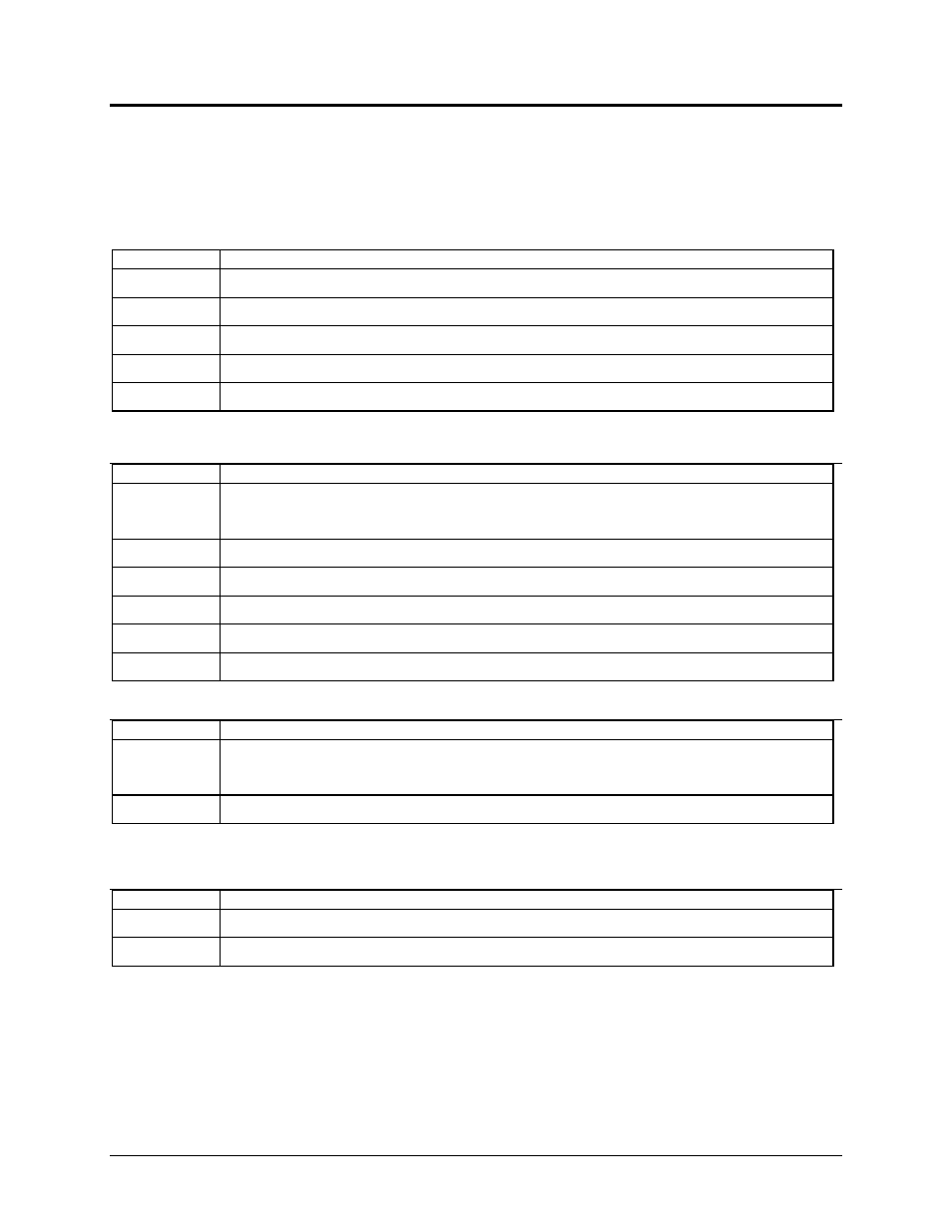
POWER/OUTPUT PLUG
Terminal No.
Usage
1,2,3
+POS, -NEG, EARTH GROUND (24VDC ONLY)
4,5
Safety relay N.O. output (dry contact)
6,7
Safety relay N.O. output (dry contact)
8,9,10
Auxiliary relay N.C., COM, N.O.
11,12
Fault relay N.O. (open when faulted)
INPUT / OUTPUT PLUG
Terminal No.
Usage
1,2
+pos, -neg External relay checking (option)
24vdc applied across these terminals when external relay is de-energized
3
Remote external zone reset (Ground to reset zone)
4,5
Auxiliary inputs (Ground to activate feature)
6
+24vdc input (Common for terminals 3,4,5) (jumper from term #1 Power/Output)
7
Optional remote RED “STOP” indicator output (Grounded when RED)
8
Optional remote GREEN “RUN” indicator output (Grounded when GREEN)
MAT 1,2,3,4 INPUT
Terminal No.
Usage
1,2
20VDC output to mat (1=blue, 2=white)
voltage between 1 & 2 alternates
3,4
Return from mat (3=black, 4=brown)
NOTE: Canadian market wiring is black, red, red, black with 18-guage wiring size.
DEVICENET PLUG (DB-9 female)
Terminal No.
Usage
2,7
CANL, CANH (twisted pair data lines)
3,6
Ground