Metal box controller, Power supply board connector layout – Pinnacle Systems STTS User Manual
Page 18
Advertising
12
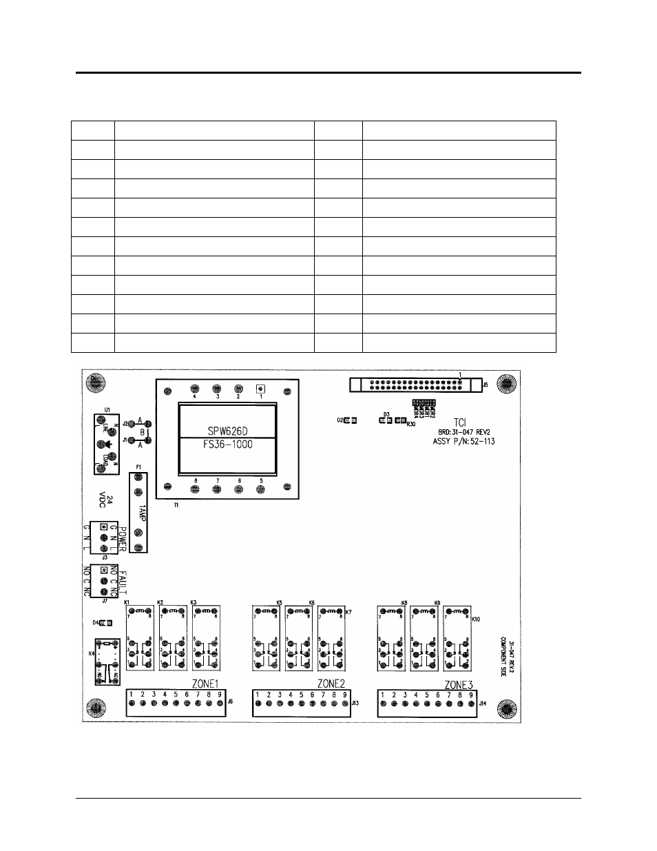
POWER SUPPLY BOARD CONNECTOR LAYOUT
Metal Box Controller
D2
+12VAC Supply
K2
Safety Output
D3
+5VAC Supply
K3
Auxiliary Output
D4
LED for the Fault Relay K4
K4
Fault Relay
F1
1A Slow-Blow Fuse
K5
Safety Output
J1-J2 AC Voltage Selection
K6
Safety Output
J3
Power Input Voltage
K7
Auxiliary Output
J5
Board Connection
K8
Safety Output
J6
Zone 1 Plug
K9
Safety Output
J7
Fault Relay Output
K10
Auxiliary Output
J13
Zone 2 Plug
T1
Transformer (AC Only)
J14
Zone 3 Plug
U1
Line Filter
K1
Safety Output
Advertising
This manual is related to the following products: