Analog Way ASCENDER 16 (LIVECORE) - Ref. ASC1602 User Manual User Manual
Page 70
70
7.3.17 Control management
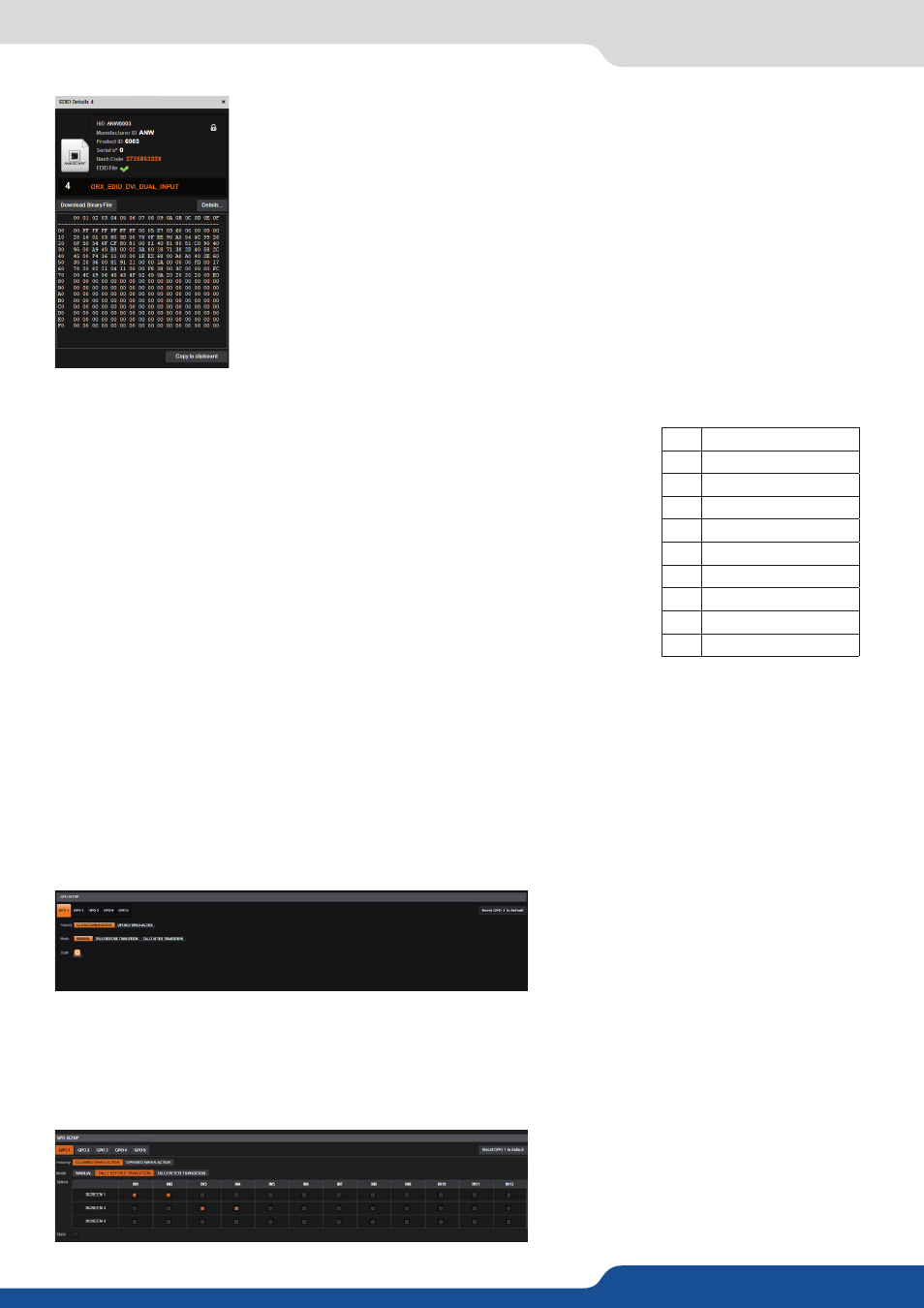
Details can be seen clicking on the magnifying glass.
Inputs EDID settings are EDIDs assigned on the inputs. There are default EDIDs, it
can be modified by dropping EDIDs from the Library. Each EDID (one per input type,
for each input) can be reset to factory. There is also a global reset for all inputs.
Tally-GPIO:
The Tally-GPIO is a set of inputs/outputs to control the device externally and
have a feedback from the device.
Here is the pin assignment for GPIO:
The pins 1 and 2 are dedicated to turn on and off the device; a switch has to be
placed between these two pins.
It works as the front panel switch: when the device is on, close the switch
will request the device to power down, if the switch is closed more than four
seconds, a forced power down is performed. When the device is off, close the
switch will turn on the device.
Only a wire with a simple switch can be connected.
GPO:
GPOs are optically isolated MOSFET, working as mechanical relays.
They all have a common pin (the 5th).
The polarity of GPO1, 2, 3, 4 and 5 have to be configured: normally open or normally closed.
The mode of the GPO can be:
- FREE:
manual mode, the state can be defined by a user action through the Web RCS or by an automation
controller)
- TALLY:
automatically generated, before or after a
TAKE
operation.
If automatically generated, it can be just before the transition (at the beginning of the transition effect) or
after (when the effect is finished).
In TALLY mode, one or several inputs have to be chosen for a screen, then when used on this screen, a GPO/
TALLY level change will occur.
1
ON/OFF switch pin1
2
ON/OFF switch pin2
3
GPI negative
4
GPI positive
5
GPO return (common)
6
GPO 1
7
GPO 2
8
GPO 3
9
GPO 4
10
GPO 5