20 installation, Ab c, For qualified installers only) – Avalon Firestyles 1080 CF Installation User Manual
Page 20
20
Installation
(for qualified installers only)
© Travis Industries
4090807
100-01193_003
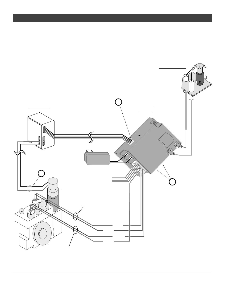
Steps for Installing the Battery Pack and Wall Switch
1. Connect the battery pack wire harness to the receiver module where it is marked “AUX” (see
Figure 12 – item “a”). At this time make sure the continuous pilot switch is set to “OFF” and the
remote switch is set to “REMOTE” on the receiver module (see Figure 12 – item “b”). You may
also wish to verify the wires leading from the receiver are fully attached.
2. Connect the DCMD wires (red and red/black) to the two wires (red and black) exiting the motor
assembly on the gas control valve (see Figure 12 – item “c”).
PRESS TO OPEN
POWER
AUX
Learn
Continuous
Pilot
Off/On
Remote/Off
ADJ
S
I
Battery Box Wires (DC Motor Drive) - 12' Length
Black, Brown, Red, and Orange wires
DCMD Wires (DC Motor Drive) - 12' Length
Red and Black/Red wires (w quick connects)
White
Green
Orange
White
Main Burner Control Wires
Pilot Flame Control Wires
Sensor ("S")
Wire (White)
Not
Used
Battery Box
Gas Control Valve
Receiver
Module
Pilot Assembly
Make sure continuous pilot
is set to "OFF" and remote
is set to "REMOTE".
a
b
c
Igniter ("I") Wire
(Orange - with
fiberglass
insulation)
AC Adapter
(wire orientation does not matter)
Figure 12