Installation, For qualified installers only) – Avalon Firestyles 1080 CF Installation User Manual
Page 21
Installation
(for qualified installers only)
21
© Travis Industries
4090807
100-01193_003
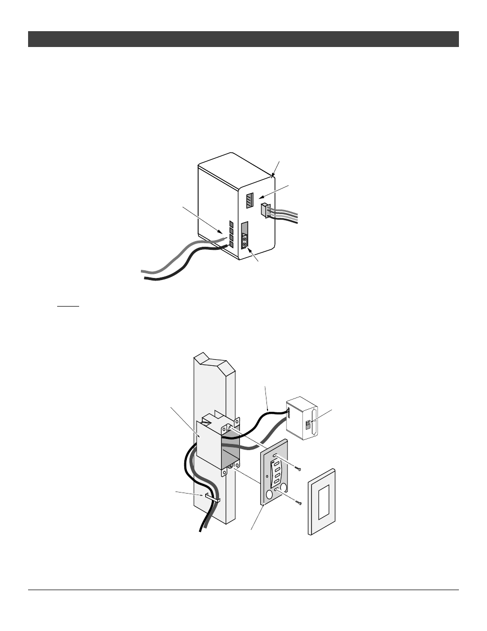
3. Determine a location for the single-gang junction box that contains the battery pack and
wireless wall switch. It must be located within 12’ of the DCMD and battery pack wires that lead
to the gas control valve and receiver module on the fireplace (see Figure 11). Mount the
junction box.
4. Insert the DCMD and battery pack wires through the junction box, leaving approximately 8” of
slack so the battery pack may be removed and the batteries replaced. Use a staple or other
means to secure the wiring to the framing – this prevents the wires from slipping out of the
junction box in the event the wires become disconnected from the battery pack (see Figure 11).
NOTE: The wiring is low-voltage (6V) and does not require a strain relief. Connect the DCMD
and battery pack wires to the battery pack (see Figure 13).
PRESS TO OPEN
The red wire goes to
the third slot, the
black wire to the
fourth (lowest) slot.
The DCMD wires are secured to the
terminal block with these screws.
Connect the battery box wiring
harness to this connector.
Back of Battery Box
Battery Box Wiring Harness
DCMD Wires
Figure 13
NOTE: You may wish to install the wireless wall switch (and cover plate) after the drywall has been
installed. Remember to mask off this area prior to drywall installation.
5. Make sure the battery box is switched to “DC Motor Drive”. Place the battery pack inside the
junction box. Attach the wireless wall switch to the junction box with the included screws.
Attach the cover plate to finalize the wall plate installation.
Battery Pack
Make sure this
switch is set to
"DC Motor Drive"
Cover Plate
(snaps into place)
PRESS TO OPEN
Latching Solenoid DC Motor Drive
Wireless Wall Switch
(includes two "CR2032" 3V batteries)
Secure to the junction box with the two
included screws.
Leave approximately 8" of slack in the wire
so the battery pack can be removed and the
batteries changed.
Junction Box (single gang)
Staple the two wires near the
junction box. This prevents the
wires from slipping out of the
junction box while the batteries
are replaced.
Figure 14