Example 7: reactive power (vars) detection, Example 7: reactive power (vars) detection -6 – Basler Electric BE1-32R User Manual
Page 16
Example 7: Reactive Power (Vars) Detection
This example illustrates a directional power relay configured to distinguish between real and reactive
power. Real power (watts) is supplied to the synchronous generator by the prime mover, and reactive
power (vars) is supplied to the field by the exciter. When field excitation is significantly reduced and the
connected system can provide sufficient reactive power to maintain the generator terminal voltage,
reactive power flows into the machine and causes it to operate as an induction generator with essentially
the same kW output. This situation causes two major problems. First, the additional reactive loading of
the faulty generator must be redistributed to other synchronous generators on the system. Secondly, a
synchronous generator is not designed to operate as an induction generator. Excessive heating results in
the damper (amortisseur) windings, slot wedges, and in the surface iron of the rotor due to the slip
frequency current flow when a synchronous generator is operated as an induction generator.
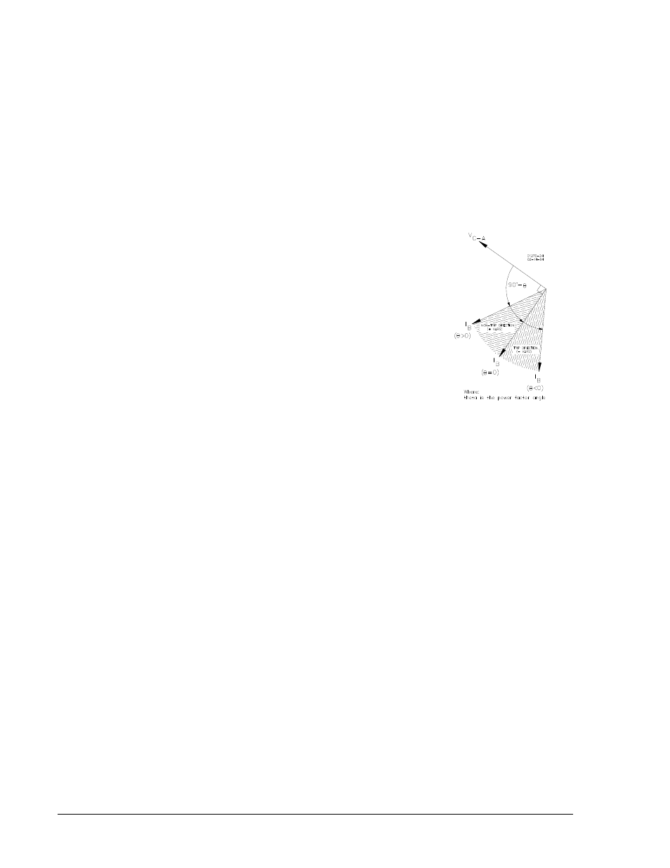
BE1-32R and BE1-32O/U Directional Power Relays are designed to respond to true power (P) as defined
by the following equation and illustrated in Figure 1-10.
P = EI (cos θ)
where: P = real power (watts)
I = effective current
E = effective EMF or system voltage
θ
= the power factor angle
However, reactive power (Q) is defined by the equation:
Q = EI (sin θ)
Using the trigonometric identity sine θ = cos(θ – 90 )
then: Q = EI (cos(θ – 90 ))
If the phase of the sensed voltage is shifted +90°, the true power relay can be used to monitor reactive
power. In practice, this can be accomplished by applying the appropriate line-to-line voltage to a true
power measuring relay designed for line-to-neutral sensing. Figure 1-11 illustrates how a single-phase
BE1-32R or BE1-32O/U can be connected to measure either real power (watts) or reactive power (vars)
flow in a three-phase system. Note the difference of phase relationship between the alternate connections
in Figure 1-11.
Figure 1-10. True
Power Response
1-6
BE1-32R, BE1-32O/U General Information
9171100990 Rev T