3 power supply, 4 in/output signals – Bronkhorst E-7000 User Manual
Page 8
BRONKHORST HIGH-TECH B.V.
page 8
9.17.004
Code for external output/input signals:
N N
-
A A A
Sensor output signal
Code
0 - 5 Vdc
0 - 10 Vdc
0 - 20 mA dc (Sinking)
4 - 20 mA dc (Sinking)
15 - 20 mA dc
0 - 20 mA (Sourcing)
4 - 20 mA (Sourcing)
FLOW-BUS
Other/Specify
A
B
C
D
E
F
G
R
Z
Module output signal
Code
0 - 5 Vdc
0 - 10 Vdc
0 - 20 mA (Sourcing)
4 - 20 mA (Sourcing)
Other/Specify
A
B
C
D
Z
Ext. setpoint/Module input signal
Code
0 - 5 Vdc
0 - 10 Vdc
0 - 20 mA (Sinking input)
4 - 20 mA (Sinking input)
Other/Specify
A
B
C
D
Z
1.3 Power supply
Each E-7000 series housing incorporates one or two power supplies.
System setup is such that the instruments that belong to the sytem can be powered.
For other applications or modifications your supplier should be consulted. The power input incorporates an
on/off switch and a fuse. For extra protection each power supply has a separate internal fuse.
1.4 In/output signals
If applicable, connection of cables carrying in- or/and output signals is further explained in the customer
system description (see appendices).
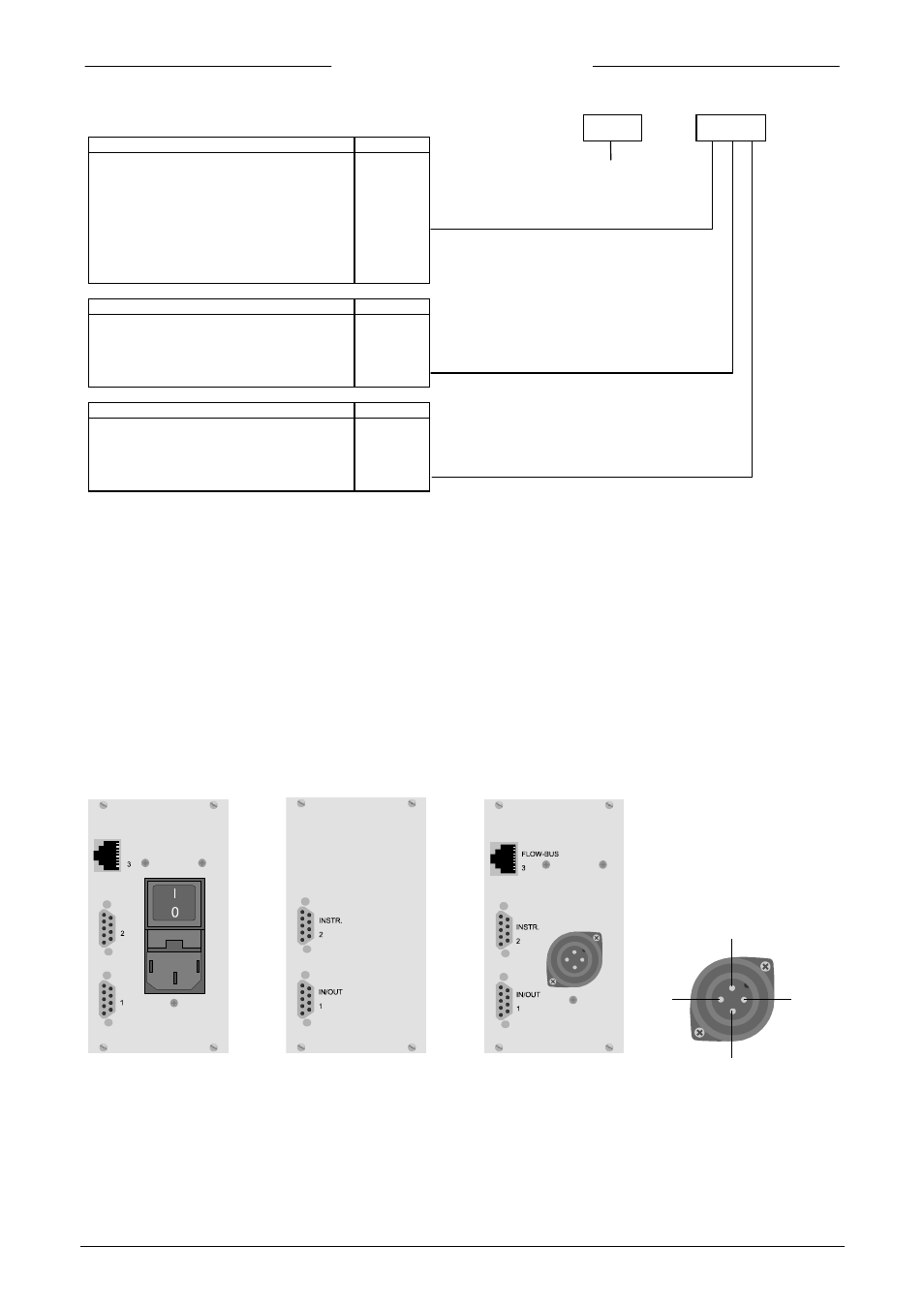
1.4.1 Rear panel connectors
for analog instruments:
FLOWBUS
w
INSTR
IN/OUT
Module
(see page 7)
1:
+24 Vdc/24 Vac
2:
0 Vdc/24 Vac
3:
not connected
PE: ground
1
2
3
PE