Bronkhorst E-7000 User Manual
Page 9
BRONKHORST HIGH-TECH B.V.
9.17.004
page 9
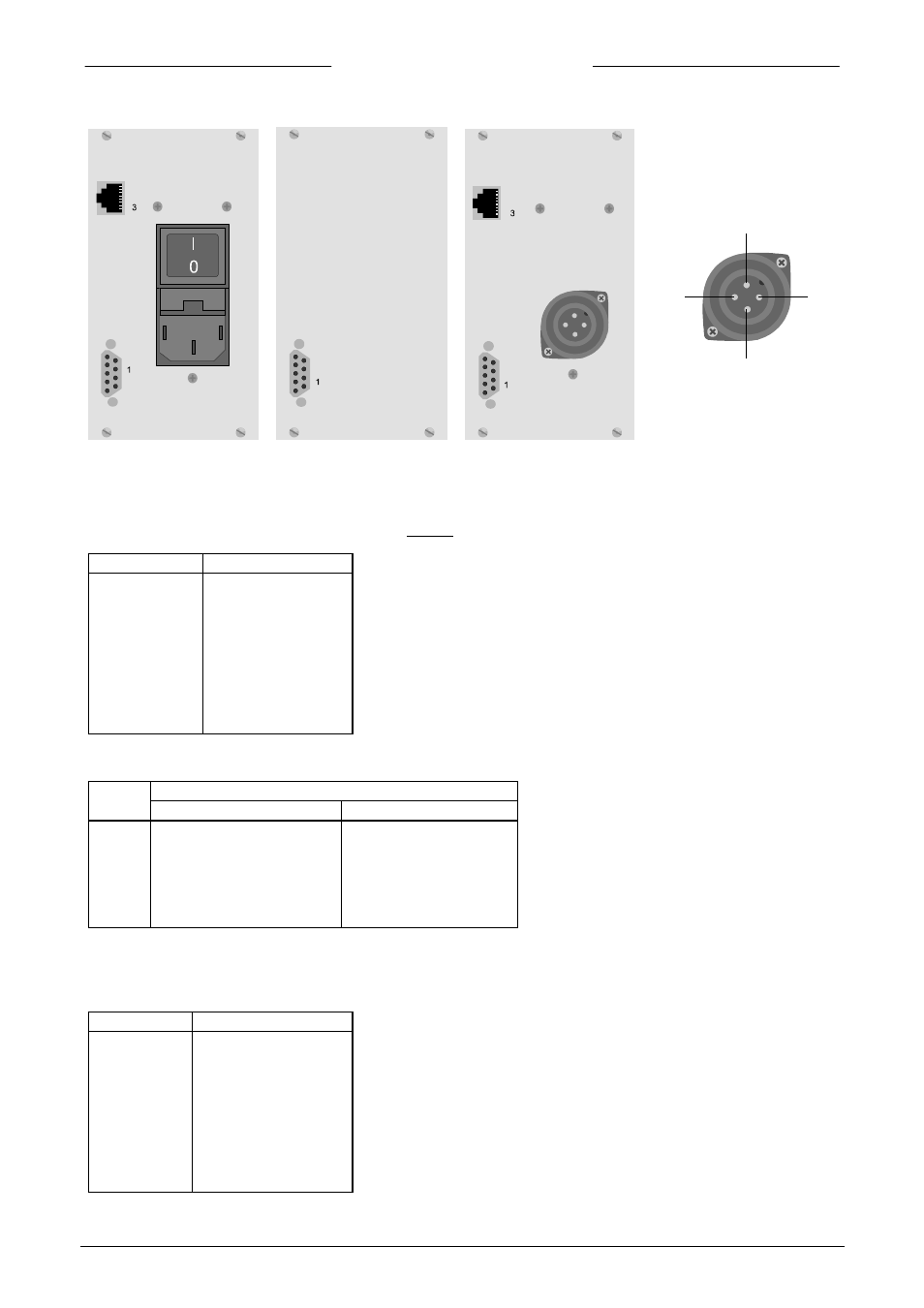
for digital instruments (FLOW-BUS):
1.4.2 Connection to measuring and controlling devices
The instrument connector (2) is a female sub-miniature 9-pin D-connector. The pin designation is according
to the Bronkhorst High-Tech B.V. standard for analog instruments.
pinnumber description
1
2
3
4
5
6
7
8
9
not connected
sensor signal
setpoint signal
0 V valve
+ valve
- 15 Vdc supply
+ 15 Vdc supply
0 V/Common
ground (shield)
Sensor- and setpointsignals are also according to one of the Bronkhorst High-Tech B.V. standards.
signal
type sensor
setpoint
A
B
C
D
F
G
0 - 5 Vdc
0 - 10 Vdc
0 - 20 mA (sinking)
4 - 20 mA (sinking)
0 - 20 mA (sourcing)
4 - 20 mA (sourcing)
0 - 5 Vdc
0 - 10 Vdc
0 - 5 Vdc
1 - 5 Vdc
0 - 20 mA
4 - 20 mA
1.4.3 Connection to remote equipment
The female in/out (1) (sub-miniature 9-pin) D-connector has the following pin configuration:
pinnumber description
1
2
3
4
5
6
7
8
9
output signal
input signal
0 V (common)
not connected
relay contact MC
relay contact NO
relay contact NC
reset input
ground (shield)
1:
+24 Vdc/24 Vac
2:
0 Vdc/24 Vac
3:
not connected
PE: ground
1
2
3
PE
FLOW-BUS
IN/OUT
IN/OUT
IN/OUT
FLOW-BUS