Bronkhorst DeviceNet slave interface User Manual
Page 14
BRONKHORST
®
Page 14
DeviceNet interface
9.17.026
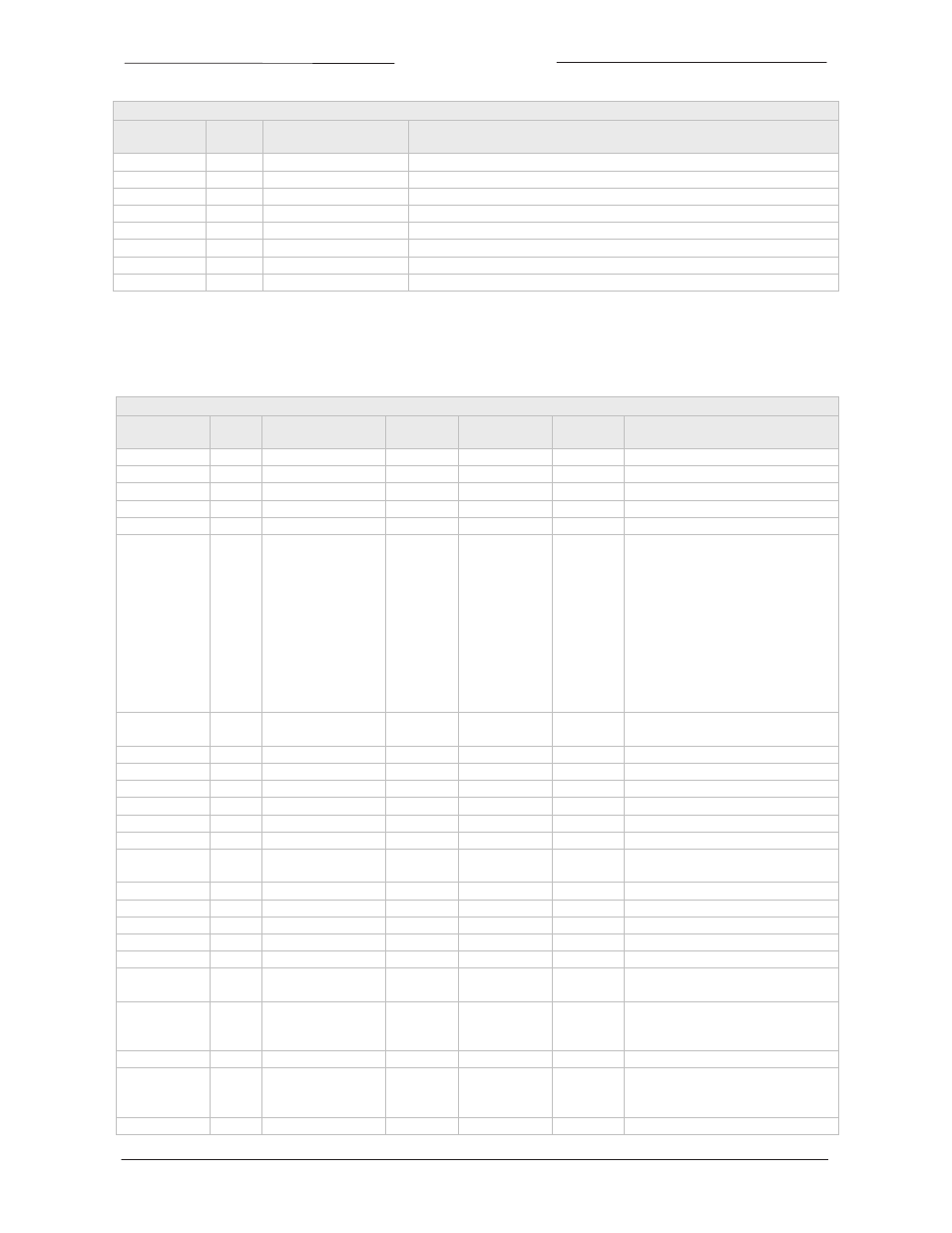
SUPERVISOR OBJECT SERVICES
SUPERVISOR
OBJECT
SERVICE
CODE
SERVICE NAME
SERVICE DESCRIPTION
0x30
0x05
Reset
Resets the device to the Self‐Testing state
0x30
0x06
Start
Starts the device execution by moving the device to the Executing state
0x30
0x07
Stop
Moves the device to the Idle state
0x30
0x0E
Get_Attribute_Single
Returns the contents of the specified attribute
0x30
0x10
Set_Attribute_Single
Modifies an attribute value
0x30
0x4B
Abort
Moves the device to the Abort state
0x30
0x4C
Recover
Moves the device out of the Abort state
0x30
0x4E
Perform_Diagnostics
Causes the device to perform a set of diagnostic routines
3.3.5 S‐Analog Sensor Object
Class Code 31 HEX
The S‐Analog Sensor Objects models the acquisition of a reading from a physical sensor in a device.
ANALOG SENSOR OBJECT’S INSTANCE ATTRIBUTES (Instance = 1)
ANALOG
SENSOR OBJECT
ATTRI‐
BUTE
ATTRIBUTE NAME
SERVICE
CODE
DATA TYPE
FLOW‐BUS Comment
0x31
0x01 Number of Attributes
0x0E
USINT
12
0x31
0x02 Attribute List
0x0E
Array of USINT
0x31
0x03 Data Type
0x0E, 0x10
USINT
0xC3=INT, 0xCA=REAL
0x31
0x04 Data Unit
0x0E, 0x10
UINT
0x1001=counts, 0x1400=sccm, etc
0x31
0x05 Reading Valid
0x0E
BOOL
0 = invalid, 1 = valid
0x31
0x06 Sensor Value
0x0E
INT or REAL
1
1,0
see attribute 3 and 4
For data unit counts the value
attribute will be in the range of
0..32767 where:
0 = no flow/pressure
32000 = max flow /pressure (100.0%)
32767 = max flow /pressure (102.4%)
Note: 32767 is max. flow for data type
INT. Max. flow REAL = 41943.04
(131.07%)
0x31
0x07 Status
0x0E
BYTE
1=High Alarm Exception,
2=Low Alarm Exception
0x31
0x08 Alarm Enable
0x0E, 0x10
BOOL
0x31
0x0A Full Scale
0x0E
INT
32000
0x31
0x11 Alarm Trip Point High 0x0E, 0x10
INT
97,1
see attribute 3 and 4
0x31
0x12 Alarm Trip Point Low
0x0E, 0x10
INT
97,2
see attribute 3 and 4
0x31
0x14 Alarm Settling Time
0x0E, 0x10
UINT
97,7
0‐65000, alarm delay (msec)
0x31
0x1C Autozero status
0x0E
UINT
1 = busy, 0 = ready
0x31
0x23 Gas Calibration Object
Instance
0x0E, 0x10
UINT
1‐8
1 = fluid 1 selected
0x31
0x69 Temperature
0x0E
REAL
33,7
Actual fluid Temperature (mini Cori)
0x31
0x6A Density
0x0E
REAL
116.15
Actual fluid Density (mini Cori)
0x31
0x6B Counter Value
0x0E, 0x10
REAL
104, 1
Actual counter value
0x31
0x6C Counter Unit Index
0x0E, 0x10
USINT
104, 2
Index of counter unit table
0x31
0x6D Counter Limit
0x0E, 0x10
REAL
104, 3
Counter lImit
0x31
0x6E Counter Setpoint
mode
0x0E, 0x10
USINT
104, 5
0 = No setpoint change
1 = Setpoint change on limit reached
0x31
0x6F Counter Setpoint
0x0E, 0x10
UINT
104, 6
Setpoint when counter limit reached
0..32000 where
0 = 0% and 32000 = 100%
0x31
0x70 Counter Unit
0x0E
STRING
104, 7
Counter unit string
0x31
0x71 Counter Mode
0x0E, 0x10
USINT
104, 8
0 = Counter Off
1 = Counter On
2 = Counter On, Up to limit
0x31
0x72 Counter Reset Mode
0x0E, 0x10
USINT
104, 9
Counter reset mode (see manual)