Bronkhorst DeviceNet slave interface User Manual
Page 19
BRONKHORST
®
Page 19
DeviceNet interface
9.17.026
3.4 P
OLLED
I/O
3.4.1 Representation
All of the above attributes in the tables from Table 2‐1 to Table 2‐16 can be accessed using Explicit Messaging. Upon
existence of an explicit connection, a Polled I/O connection can also be established and coexist. Once the Polled I/O
connection has been established, the device will be able to accept and process the Polled I/O requests. For example, if
Instance #7 has been selected as Output IO Assembly Instance, two data bytes representing the new setpoint shall be
appended to the Polled I/O request for setting a setpoint. If the Data Unit attribute were 0x1001 as the code for
“Counts”, the value of the setpoint bytes will be an signed integer where 0x7D00 (*) represents 100% flow and 0x0000
represents 0% flow. Upon reception of the Polled I/O Request, if Instance #2 has been selected as Input IO Assembly
Instance the DeviceNet MFC will respond with a Polled I/O Response carrying with it three data bytes as described
below:
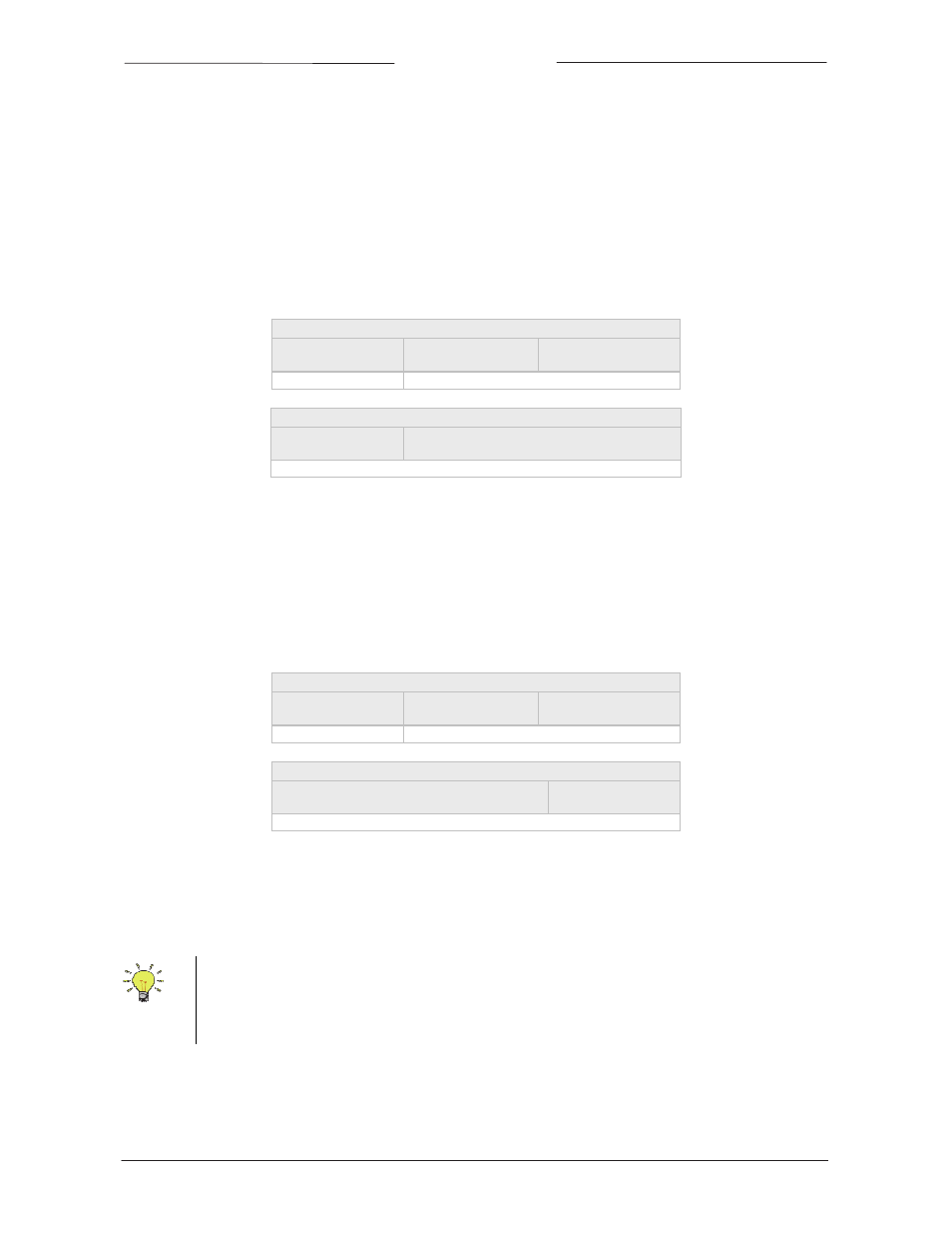
Polled I/O Response’s Data Field using Counts as Data Unit
Byte0:
Exception Status
Byte1:
Indicated Flow (LSB)
Byte2:
Indicated Flow (MSB)
BYTE
INT (0x7D00 = 100%)
Polled I/O Request’s Data Field using Counts as Data Unit
Byte0:
New Setpoint (LSB)
Byte1:
New Setpoint (MSB)
INT (0x7D00 = 100%)
Note that if “Counts” has been selected for the Data Unit attribute of the Analog Sensor and Controller object (i.e., the
value of these attributes is 0x1001), then the Indicated‐Flow bytes in the Polled I/O Response represent the same
information as that of the New‐Setpoint bytes in the Polled I/O Request (i.e., 0x0000 represents 0% flow and 0x7D00
(*) represents 100% flow). However, if the “Data Unit” attribute of the Sensor and the Setpoint object are 0x1400, the
value of the indicated flow and setpoint will be in Standard Cubic Centimeter (SCCM). Note that the setpoint and the
indicated flow can be set with different data unit (i.e., Counts for Setpoint and SCCM for Indicated‐flow or vice versa).
Since the Indicated‐flow and Setpoint attribute are integer, if used in SCCM mode the value of these attribute can not
exceed 32767 SCCM. Therefore the SCCM mode shall not be used for MFCs having gases with the full‐scale exceeding
32767 SCCM or having the Full‐scale loaded with SLM data unit.
Polled I/O Response’s Data Field using SCCM as Data Unit
Byte0:
Exception Status
Byte1:
Indicated Flow (LSB)
Byte2:
Indicated Flow (MSB)
BYTE
INT (0 to Full Scale)
Polled I/O Request’s Data Field using SCCM as Data Unit
Byte0:
New Setpoint (LSB)
Byte1:
New Setpoint (MSB)
INT (0 to Full Scale)
The tables above show some examples of the Polled I/O setting. There are eight (8) IO Assembly Instances that the
user can choose from; 4 for input and 4 for output. These instances are specified in the MFC Device Profile document.
See next paragraph for more details.
(*) 100% Measured Value indication for Bronkhorst instruments is 0x7D00 (signed integer). Maximum
value for Measured Value is 102.4 %, which is: 0x7FFF. Other suppliers may use different ranges for
Measured Value. Via Full Scale: attribute 0x0A of object 0x31, analog sensor, it is possible to readout
the signed integer value used for 100%.