Polarity, Limiter, Limiter threshold – BSS Audio FDS-355 OMNIDRIVE Owner's Manual User Manual
Page 28: Band gain, Delay link
2 8
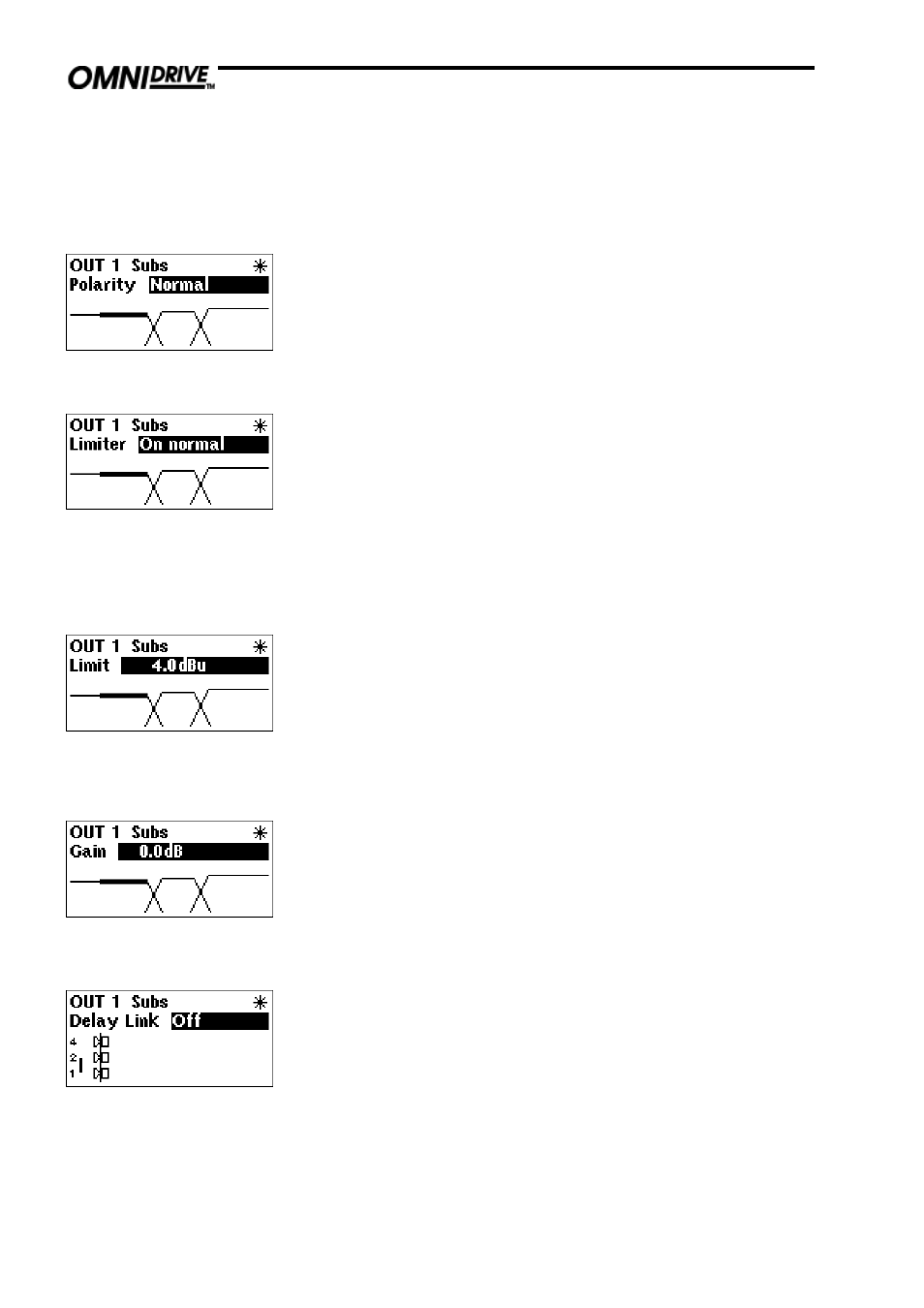
Polarity
The polarity invert function. Default is uninverted. Turning the parameter
wheel clockwise will invert the polarity of the output. Turning anticlockwise
will return the polarity to uninverted.
Limiter
The limiters can either be set to ON NORMAL, or ON FAST; the fast setting
having a faster attack time. It is also possible to disable the protective limiters
by turning the parameter wheel anticlockwise to toggle the display to OFF.
When the limiters are turned OFF, the red OVER indicator will illuminate as a
warning.
Limiter settings are preserved when a user saves a program - limiters will
automatically be set to ON NORMAL if the limiters were on.
NOTE: BSS Audio cannot accept any liability for any damage caused by
disabling the protective limiters in the FDS-355. This function is used totally
at the discretion of the user.
Outputs menu
Limiter threshold
With the limiters enabled, the band limiter threshold can be adjusted by
turning the parameter wheel to set the desired value to match the sensitivity
of the amplifier in use. The default units are dBu, but can be changed to mV.
Refer to section 7.0; Utilities menu for details on how to change this.
BSS Audio recommends setting the limiter thresholds below the amplifier
clipping sensitivity by about 2dB. This prevents any transient overshoot driving
the amplifier into clip and so damaging your loudspeakers. When limiters are
disabled, the threshold setting determines the output meter sensitivity.
Band gain
To adjust the relative gain of the band output, turn the parameter wheel to
achieve the desired level. This is independent of the output TRIM control on
the front panel, and is additional to any level added by TRIM. Band Gain is
stored as part of the program memory, whereas trim is not.
Delay link
The Delay Link option allows you to control several band delays with a single
adjustment. This means that once all the drivers in a single cabinet have been
aligned, the whole cabinet can be delayed relative to the input signal, or
another cabinet, by linking these band delays as one. Any offsets applied
before linking will be retained after linking.
In the Delay Link screen, turn the parameter wheel until the desired linking
configuration is shown. The linking setup is shown by a graphical
representation, and is also described above the diagram.