2 rear panel - mono input channel module 8411, Rear panel - mono input channel module 8411 -9 – Cadac S-Type User Manual
Page 27
Advertising
Mono input module 8411
4-9
Revision S2005-6
S-Type
715
5HDU#SDQHO#0#PRQR#LQSXW#FKDQQHO#PRGXOH#;744
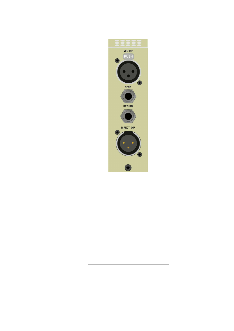
MICROPHONE INPUT
INSERT SEND
INSERT RETURN
DIRECT OUTPUT
Inputs and outputs are electronically balanced and con-
nected via 3-pin XLRs and follow the wiring convention:
PIN 1 = Screen
PIN 2 = In-phase signal (hot)
PIN 3 = Out-of-phase signal (cold)
The 0.25” TRS jack connectors use the wiring conven-
tion:
TIP = In-phase signal (hot)
RING = Out-of-phase signal (cold)
SLEEVE = Screen
IMPORTANT NOTE: Pin 1 on XLR connectors and the
‘sleeve’ connections on the jack sockets are connected
to the FRAME. This is to ensure that the console can
comply with the Electromagnetic Compatibility (EMC)
directive.
Advertising