1#0l[#exv#frglqj – Cadac S-Type User Manual
Page 58
APP-II
S-Type
Revision S2005-6
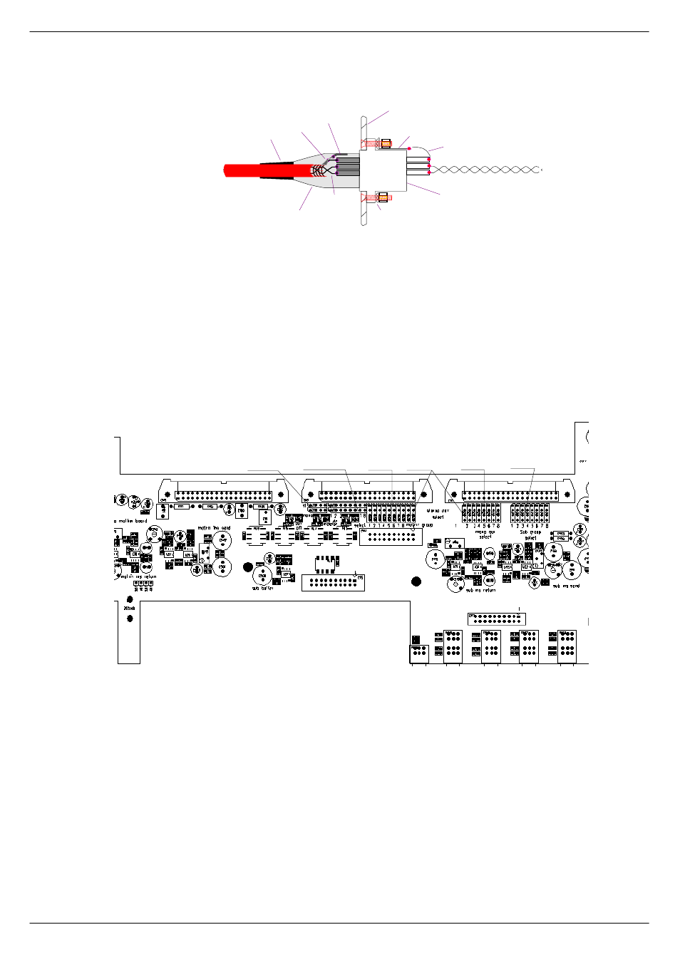
The chassis half of the connector is bonded to the metalwork with the usual nuts,
bolts and spiky washers. The solder tag should be as long as possible so that the
length of the 'short wire' is a minimum. The twisted pair (from the signal pins - pin 2 &
pin 3) are soldered onto the motherboard adjacent to the 'input RFI filter' compo-
nents.
%1#0L[#EXV#FRGLQJ
The module mix bus coding is manually selectable. For details about how to do this,
see below:
1.
Group module 1 or 2 should be set to stereo, all others to mono.
2.
Select DC Master by inserting a 2-way jumper in position to select 1 - 8.
3.
Select appropriate matrix group 1 - 8 with the link.
4.
Out of the 8 auxiliary sends, the first two are in stereo and so requires two
jumper links, the remaining 6 aux’s require one link.
5.
Finally, in the block of 8 links for the sub-groups - place the link in position 1 - 8.
NOTE: The left hand group module should be number one, working towards right
incrementing one at the time.
All links in the same module must be the same number.
T W IS T E D P A IR
W IT H B R A ID ED
S C R E E N
S T R A IN R ELIEF
P IG T A IL
S H ELL G R O U N D T A G
X LR
M E T A L S H E LL
W IT H C O N D U C T IV E FIN IS H
T W IS T E D P A IR
M E T A L P A N EL
S P IK Y W A S H ER
LO N G S O LD E R T A G
S H O R T W IR E
T W IS T E D P A IR T O FILT E R O N P C B
X LR C H A S S IS C O N N E C T O R W IT H
C O N D U C T IV E S U R FA C E A N D
M U LT I-P O IN T B O N D T O S H E LL
O F C A B LE C O N N E C T O R
FIG APP -1. XLR connections.
5. Sub-Groups
select
Aux Mono
select
3. Matrix
select
2. DC Master
select
4. Aux stereo &
select
1. ST/Mono
select