2 channel setting, Channel setting – Daktronics Remote Control System RC-100 User Manual
Page 17
RC-100 Base Station
9
Keep in mind the following when using the Gen I mode of operation:
Gen I handheld controllers or Base Stations will not operate in Function “5”.
All Base Stations operating at the same location must be set to the same Function.
Gen I handheld controllers display ED14905 Version 1.6 or lower on the LCD at
power-up. Gen I Base Stations are labeled ED14906 Version 2.1 or lower.
Gen II handheld controllers display ED14905 Version 2.2 or higher on the LCD at
power-up. Gen II Base Stations are labeled ED14906 Version 2.2 or higher.
3.2 Channel Setting
The wireless Base Station and wireless handheld device use internal radio modules to
communicate. The radios on both the wireless handheld and wireless Base Station device can
be set to any channel ranging from 1-15. “Channel 1” is the default channel used by
Daktronics for single base-station installations.
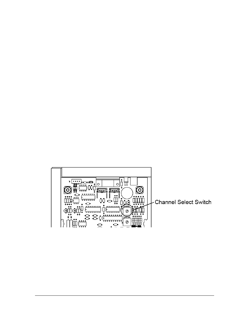
Refer to Figure 6 for the wireless Base Station circuit board assembly drawing.
To access the circuit board:
For external Base Station enclosures, remove the two screws securing the top cover,
and lift it off.
For internal Base Stations, refer to the scoreboard/display manual for component
location and access instructions.
After exposing Base Station circuit board, use a small flathead screwdriver to turn the “S1”
rotary switch labeled “CHANNEL” to the desired channel.
Note: The wireless handheld and Base Station must be set to the same channel in order to
communicate. To select the channel in the wireless handheld controller, refer to Section 4.1.
Two server Base Stations cannot be powered up in the same area with the same channel
setting, or they will interfere with each other. To avoid this, on power-up the server Base
Station checks to see if there are any other servers located nearby. If another server is
detected, the “IN RANGE” LED (Figure 10) will flash quickly to indicate interference, and
continue to flash until the channel is changed or the conflicting Base Station is turned off.
Figure 6:
Channel Select Switch (Internal Receiver)