5 wireless base station leds, Wireless base station leds – Daktronics Remote Control System RC-100 User Manual
Page 22
14
RC-100 Base Station
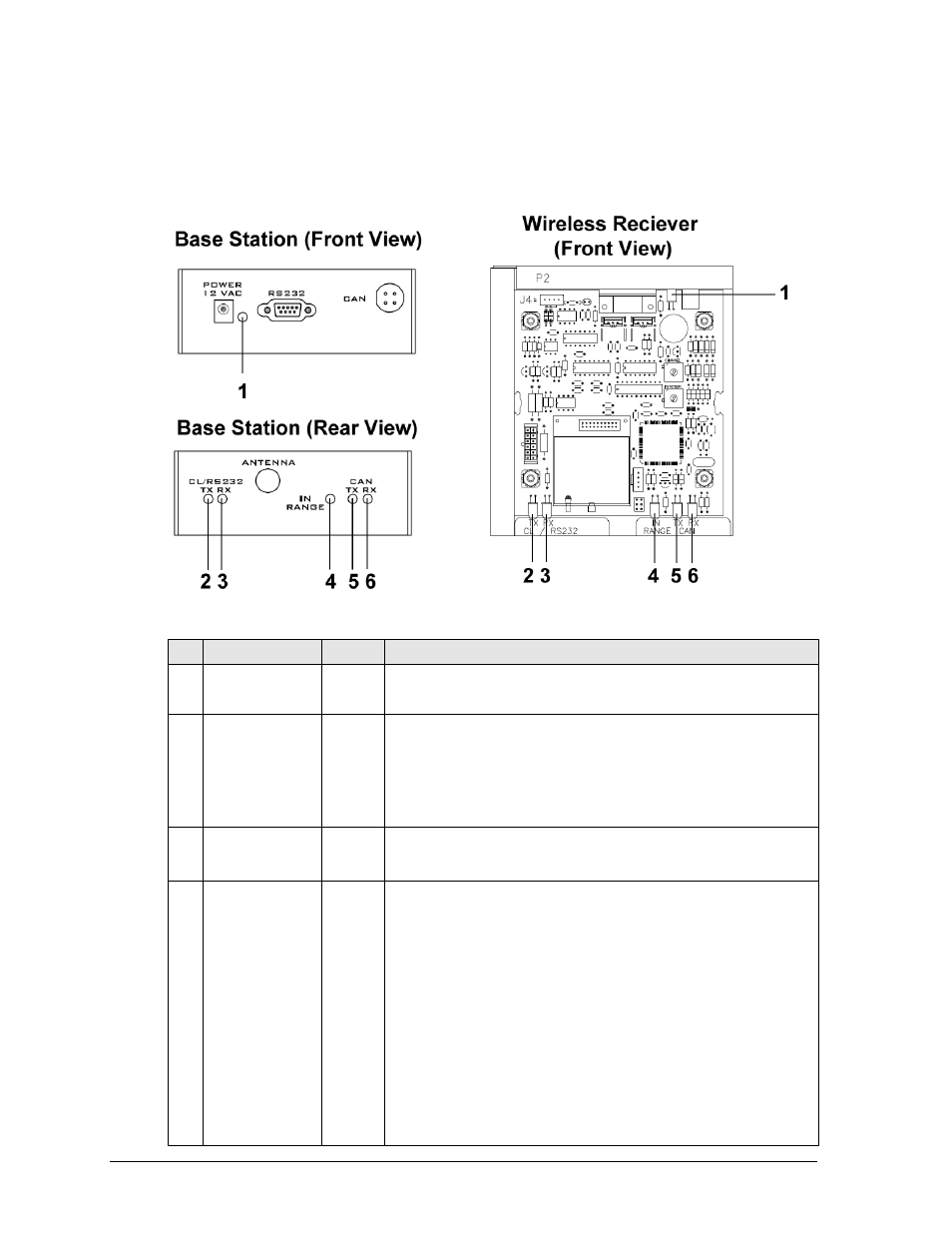
3.5 Wireless Base Station LEDs
The wireless Base Station circuit board includes several light-emitting diodes (LEDs) for
diagnostic purposes, as shown in Figure 10 and described in the table that follows.
#
LED
Color
Function
1
POWER
Green
This LED illuminates when the Base Station or receiver is
connected to a power source
2
CL/RS232 TX
Red
This LED flashes when the Base Station transmits Current
Loop (CL) or RS-232 data via wire:
Current Loop output is used to control scoreboards.
RS-232 output is used to communicate with external
devices, such as a compu
ter with DakTennis™.
3
CL/RS232 RX
Green
This LED flashes when the Base Station receives Current
Loop (CL) or RS-232 data from another device via wire.
4
IN RANGE
Amber
On a server Base Station, this LED flashes several times at
start-up to indicate that it is searching for other server Base
Stations on the same channel within range. If one is found,
this LED flashes continuously to indicate that only one
server Base Station is allowed on a given channel. Once in
operation mode, this LED will either be on or off to indicate
whether or not one or more handheld devices are currently
connected to the Base Station.
On a client Base Station, this LED is on whenever it is
connected to a server Base Station.
This LED also shows sync status. Refer to the Section 3.3.
Figure 10:
Wireless Base Station LEDs