Caution, Master out and secondaryunit in, Saddle stitching-foot switch use only – MBM Corporation BINDERYMATE 2 User Manual
Page 14: Work guides, Changing work thickness
12
Master Out and SecondaryUnit In:
These outlets are only for use with the "Multiple
Stitch Accessories".
Saddle Stitching-Foot Switch Use
Only:
Switch off power. Swing up front guard assembly.
Turn the trip lever knob counter clockwise, and
move the work trip all the way back. Position the
table/saddle for saddle stitching. Swing down the
front guard assembly. Slightly loosen the two knobs
(counter clockwise) securing the front sliding guard
to the front guard. Allow the front sliding guard to
drop to the saddle position. Retighten the two knobs.
Plug the foot switch cord into foot switch outlet on
rear control panel (work trip is then automatically
passed). Switch power on. Load work from either
side and step on foot switch to cause a stitch.
CAUTION
AVOID DAMAGE TO YOUR
STITCHER BY FOLLOWING THESE
RULES:
1. Never operate your stitcher with wire
feeding unless you have work material
between the clinchers and benderbar.
2. Do not drive one stitch on top of
another.
Work Guides:
A. Side Guides: To adjust side guides pop-up the
pins at the end of each guide, loosen the screw
knob beneath the table, position guides as desired,
and retighten the screw knob.
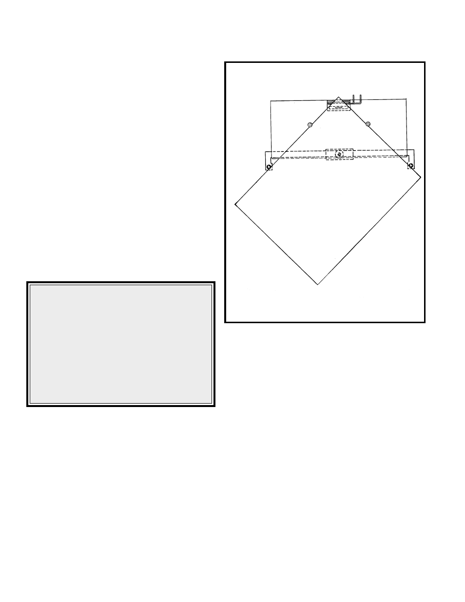
B. Corner Stitch Guides-Table Use Only: Pop Up
the pins located in the table and the pins located
at the end of each side guide. Using your work
as a set up tool, position and secure the side
guides as indicated in figure 13. Switch off
power, swing upfront guard assembly, and move
the work trip all the way forward. Swing front
guard assembly back down and switch on power.
Push work into corner guided area of table until
depression of work trip causes a stitch.
Changing Work Thickness:
Changing work thichness will probably require a
change of the wire draw length used to make a
stitch. This is done by raising or lowering the face
plate. To change face plate position switch off
power; swing front guard assembly up to the second
detente position; loosen the faceplate screw
(Located directly above M2000 on the face plate),
move the position lever up for more wire or down
for less wire, retighten faceplate screw, and swing
down front guard.
Figure 13
(QF27F8)