Do not remove or adjust these two screws – MBM Corporation BINDERYMATE 2 User Manual
Page 32
30
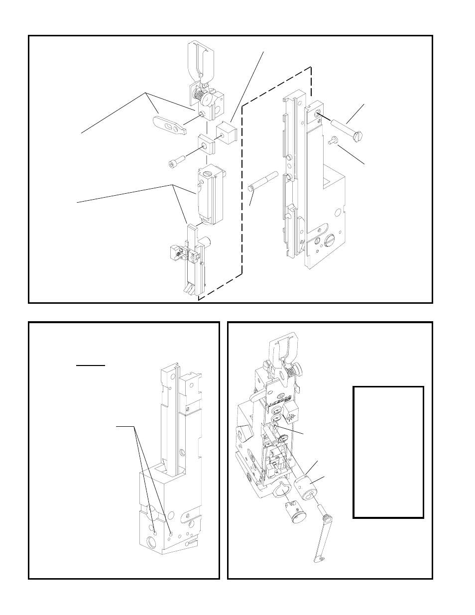
REMOVING AND DISMANTLING M2000 HEAD
F
E
21. Slide tension spring bracket
and adjusting lever from top.
20. R e m o v e
screw
22. Loosen face plate clamp screw and slide out face plate
locating block.
23. Slide the driving slide and bender
bar assemblies from the top. When
reassembling, hook bender bar to
driving slide before sliding into
place. This must be assembled as
a complete unit.
19. Remove
rotator
operating
cam
stud.
18. R e m o v e
r o t a t o r
o p e r a t i n g
cam stud
screw.
DO
NOT
REMOVE
OR ADJUST
THESE TWO
SCREWS.
The screws
are factory set
to control the
s u p p o r t e r
lever location.
Caution
When reassembling,
make certain that pin
(Index A) is visible and is
aligned with slot (Index
B) of rotator operating
cam (Index C). If not
assembled in this way,
the bonnet casting will
crack or break on the
next cycle under power.
It is recommended that
the stitcher be cycled by
hand to test that proper
reassembly procedure
has been followed.
A
B
C
G
(CTTT2605T3 Scene 19)
(CTTT2605T3 Scene 21)
(CTTT2605T3 Scene 20)
How to Install rotator
operating cam