D. to adjust clincher points height (figure 20) – MBM Corporation BINDERYMATE 2 User Manual
Page 23
21
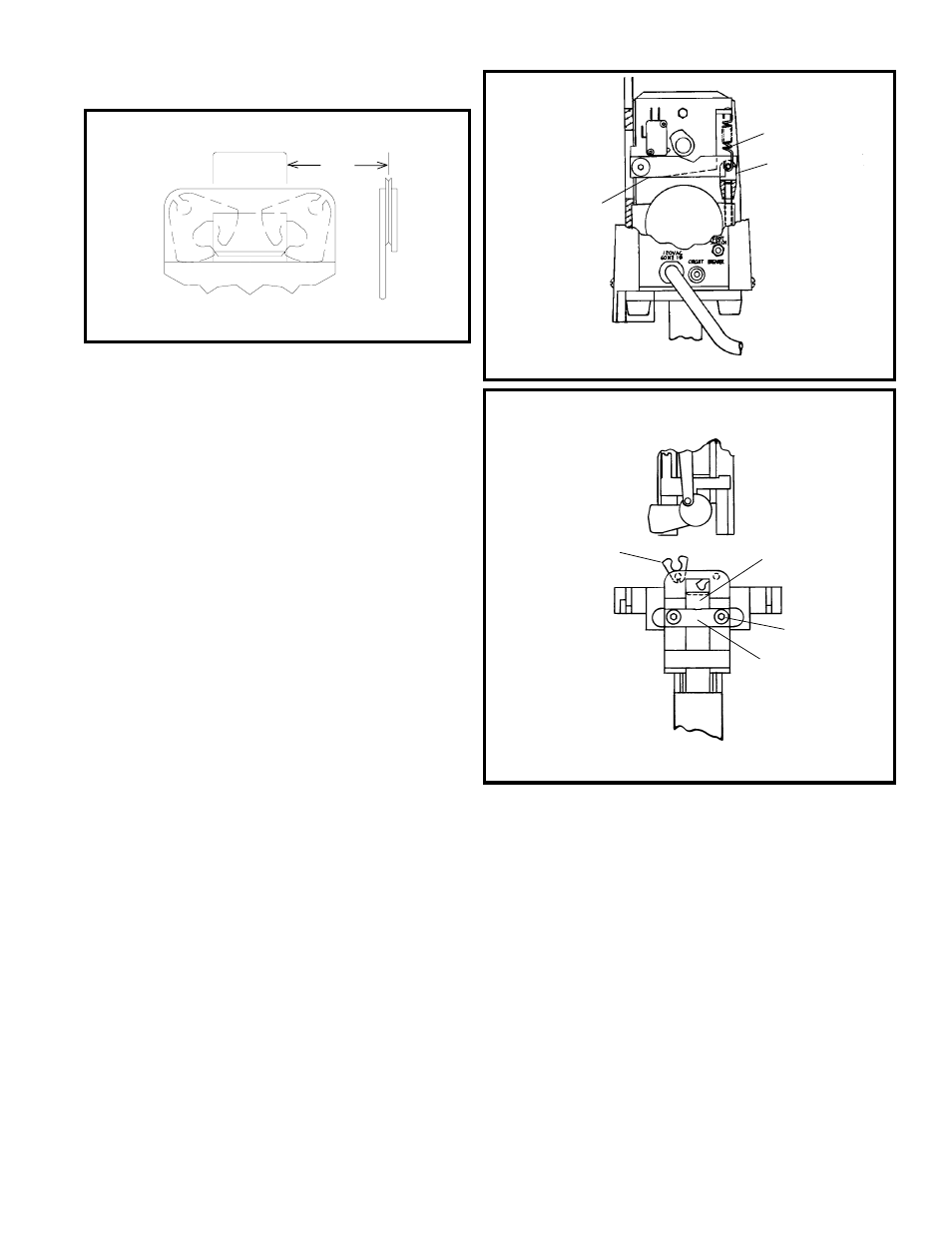
D. To Adjust Clincher Points
Height (Figure 20)
1. Turn off power and unplug power cord.
2. Remove wire coil, washer, compression spring
and stud.
3. Swing up front guard assembly to 1st detent
position.
4. Unscrew the four screws securing cover and
remove cover.
5. Unhook and remove the extension spring (Index
A).
6. Lift clincher operating lever (Index B) away
from clevis (Index C) and turn clevis clockwise
to lower the clinchers, counterclockwise to raise
the clinchers. Note: clinchers will raise or lower
.025" per 360 degree turn of clevis.
7. Reassemble unit.
If the clinchers points are broken, the stitch legs
will not clinch and/or be deformed. Reverse or
replace the clincher points.
E. To Reverse or Replace Clincher
Points (Figure 21)
1. Remove the two screws (Index A) securing the
clincher slide brace (Index B). Remove brace.
2. Move clincher slide away from clincher points
(Index C).
3. Raise the clincher points, and reverse or replace.
4. When reassembling, push the clincher points
down so that the top lip of the clincher slide
(Index D) will engage the center of the clincher
points. Note: Clincher slide must move freely
up and down after reassembly.
The proper alignment of the clincher under the
formers is one of the most critical adjustments on
the stitcher. Therefore, extreme care should be
taken to align the clincher so that both legs of the
stitch strike the clincher at the same time with equal
spacing from the outside edges of the grooves (See
Figure 19). Also, the clincher must be aligned with
the bender bar grooves of the head from front to
rear so that the legs enter the clincher at the widest
section of the clincher grooves.
Figure 19
(SK852F)
Figure 20
(QF27F10)
Figure 21
(QF27F11)
B
A
C
C
D
A
B
Stitch