M. wire cutter operating slide, N. proper wire, O. rotator (figure 28) – MBM Corporation BINDERYMATE 2 User Manual
Page 28
26
M. Wire Cutter Operating Slide
The wire cutter operating slide actuates the lower
wire cutter which acts as the cutting knife. If the
slide is worn or broken, the wire cutter is not
actuated. Replace the operating slide.
To Replace The Wire Cutter Operating Slide:
1. Cut the wire at the bracket and pull the loose
end out.
2. Remove the stitcher head assembly.
3. Lift end of spring (Index L, Figure 28) out of
rotator.
4. Swing the spring up to disengage it and lift out.
5. Slip the rotator operating cam (Index M, Figure
28) forward and off the stud.
6. Pull the rotator forward.
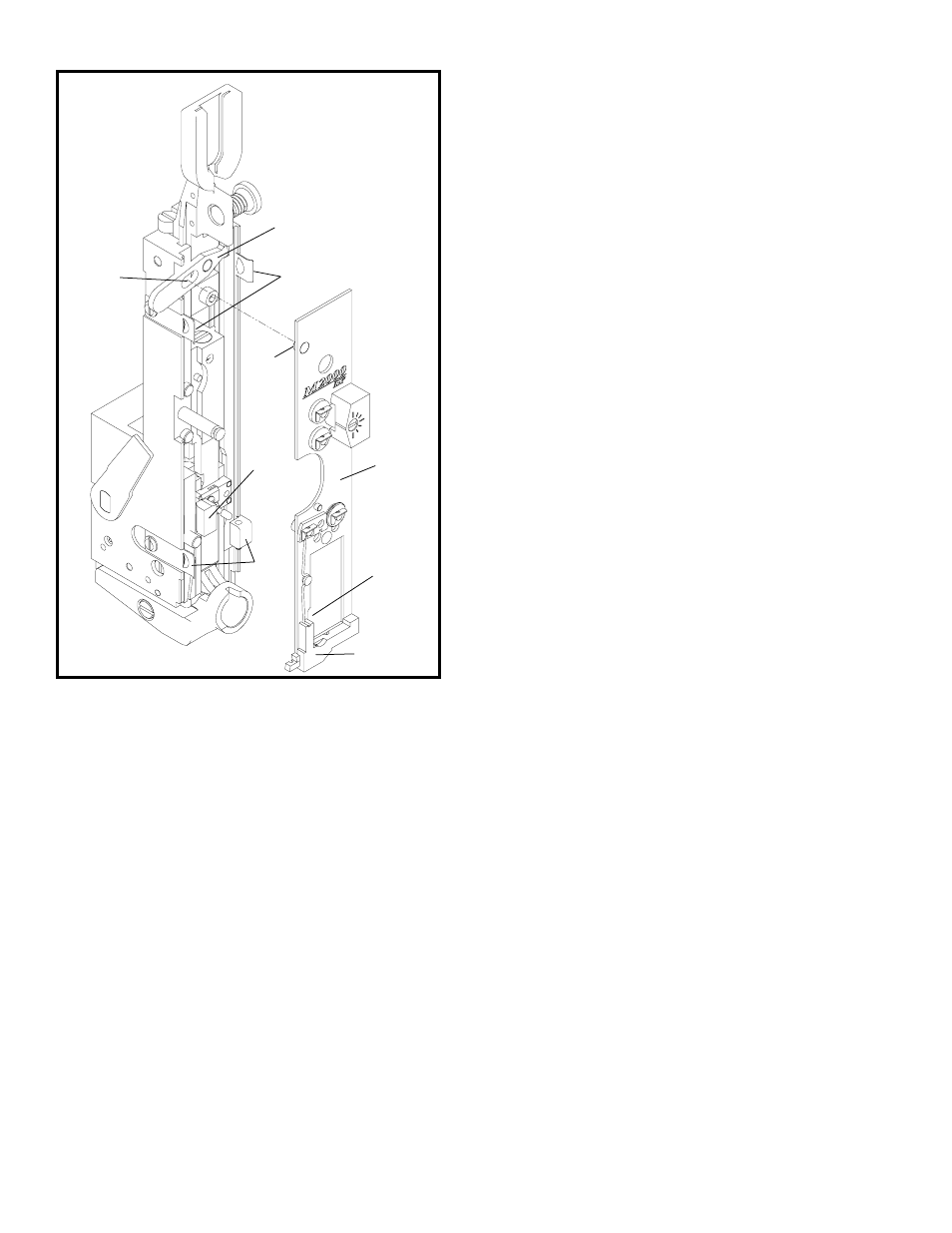
7. Loosen the two face plate retaining clips (Index
A, Figure 29) and rotate them downward.
8. Push two face plate retaining clips (Index F)
outward while lifting face plate up, or remove
retaining clips to release face plate.
9. Position grip spring housing (Index G) between
tension pawl spring retainer (Index H) and cutter
housing (Index I).
10. Remove face plate (Index B) by sliding face
plate to the left and lifting up.
11. Remove the cutter operating slide (Index I, Figure
28).
12. Insert a new cutter operating slide.
13. Reassemble
N. Proper Wire
The Bindery Mate is designed to use 25 gauge (.020"
diameter) 120,000 to 159,000 psi tensile strength
bookbinders wire.
If the wire used is larger than the bender bar grooves
were designed for, it will fracture at the stitch corners
and come out in pieces. Also, serious damage to
the stitcher may result. If the wire used is smaller
than the bender bar grooves were designed for, the
legs of the stitch do not fit snugly in the grooves and
may tend to buckle when they strike the work material
because they are not fully supported.
O. Rotator (Figure 28)
The rotator (Index J) (1) recieves the wire from the
cut-off die, (2) holds the wire while it is being cut,
then (3) turns it to a horizontal position, moves it
under the bender bar grooves and (4) supports the
wire while it is being formed into a "U-shaped"
stitch.
The wire lead-in-funnel of the rotator must be aligned
with the wire as it comes through the wire cutters.
If the rotator is improperly aligned, the wire hits the
rotator and buckles. Adjust upper two wire
straightners until wire slips past rotator. Burrs on
the rotator prevent the wire from entering the rotator.
This causes wire buckling. Remove the rotator and
polish the lead-in radius.
The magnets in the rotator hold the wire firmly in
the rotator. If a magnet is broken or chipped the
wire may fall out. To determine if the rotator has
the proper holding strength, remove the rotator and
insert a cut length of wire in the rotator. Hold
rotator between thumb and forefinger. Attempt to
jar wire loose by hitting heel on hand on top of
table or against other hand. With proper magnetic
holding force wire will remain in rotator. With
Figure 29
(CTTT2605T3 Scene 13)
E
C
D
I
H
G
F
B
A