Assembly (figures 1,2,3) – MBM Corporation BINDERYMATE 2 User Manual
Page 7
5
Section
3
ASSEMBLY, LUBRICATION
INSTALLATION
Note:
These instructions must be followed to insure
proper installation, efficient operation and the
prevention of serious damage to your stitcher.
Before Unpacking:
Examine the outside of the crate or carton for any
visible damage. If damaged DO NOT UNPACK
THE STITCHER. Notify the carrier who delivered
the stitcher.
After Unpacking:
Examine your stitcher carefully for any damage in
transit. If damaged, DO NOT INSTALL THE
STITCHER. Notify your nearest representative and
the carrier who delivered your stitcher.
Make certain that you get a signed copy of the Carrier
Inspectors Report of the damage incurred
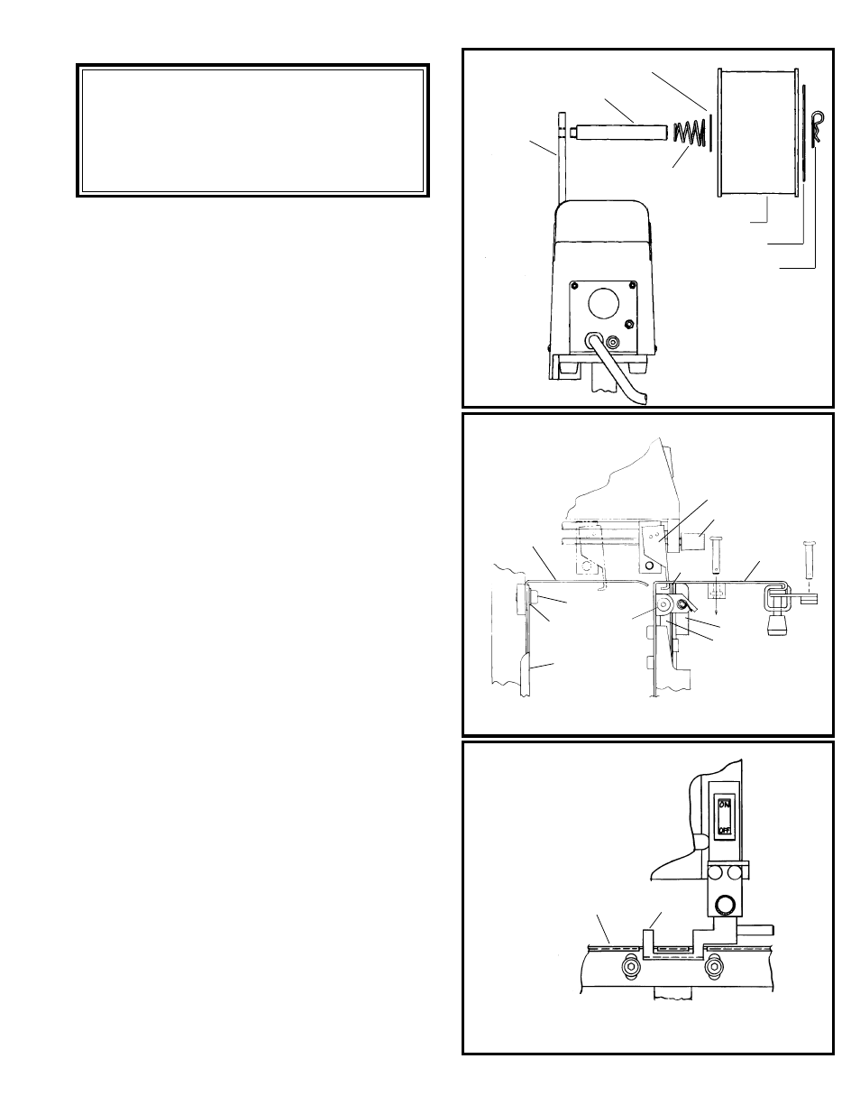
ASSEMBLY (FIGURES 1,2,3)
1. Clamp the Bindery Mate to a table or bench (see
"Mounting" page 3). Assemble per figure 1.
2. Install Table/Saddle (Index A) to Table and
Clincher Bracket (Index B) using the two
shoulder screws (Index C). Shoulder of screws
should extend through table and bottom out inside
of table/clincher bracket.
3. Turn Trip lever Knob (Index D) counter
clockwise and move the work trip (Index E) all
the way toward the clincher (Index F). Install
the Auxiliary Table (Index G) and Paper Guide
(Index K) to the stand using the two .25-28 x
.375 socket head cap screws and flat washers
(Index H,I). The top surface of the auxiliary
table should be at the same height as the main
table. NOTE: The auxiliary table MUST
NEVER TOUCH THE WORK TRIP OR
STITCHER WILL ACTIVATE (SEE
FIGURE 3).
4. Install Wire Guide Spring into wire guide bracket
of M2000 Head.
Wire Spool Washer
Wire Spool Stud
Support
Conical Spring
Spool Retainer
Coil of Wire
Hair Pin Cotter
NOTE: Slide coil of wire onto
spool stud so that the wire will
feed upward from the rear
NOTE: AUXILIARY TABLE "G"
MUST NEVER TOUCH WORK
TRIP "E"
Figure 1
(QF27F1)
Figure 2
(QF27F2)
Figure 3
(QF27F3)
A
E
D
B
J
K
I
H
G
G
E
F
C