L. wire cutters: (figure 28) – MBM Corporation BINDERYMATE 2 User Manual
Page 27
25
When the face plate (Index E) is adjusted (See
"Changing Work Thickness", page 12) a pivotal
action (at point F) changes the position of the grip
slide. When the face plate is raised, it moves the
grip release slide down. The gripper can then remain
closed longer, on the downstroke, feeding more wire
for the stitch. When the face plate is lowered, it
moves the grip release slide up. The gripper will
open sooner on the downstroke, feeding less wire
for the stitch.
If the grip is weak, uneven wire draw will result.
Replace the grip spring. If the contact points on the
grip release slide and/or the bender bar latch are
worn, wire adjustment will not remain accurate.
The face plate stops the bender bar assembly at the
top of its stroke and allows the bender bar latch to
close the grip. When the face plate is too high, too
much of the upstroke has been used before the bender
bar hits the face plate. In the remaining portion of
the upstroke, the driver bar cannot continue upward
enough to release the bender bar latch so that it can
close the grip.
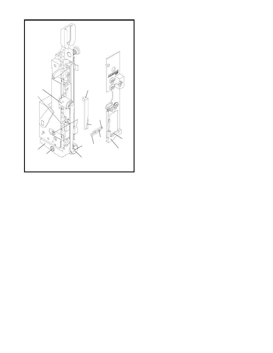
L. Wire Cutters: (Figure 28)
The purpose of the wire cutters is to shear the wire
cleanly. There are two wire cutters, upper and
lower. The upper wire cutter (Index A) recieves
wire from the grip through the wire cutter lead-in-
hole (Index B). It also serves as the cut-off die.
The lower wire cutter (Index C) is the cutting knife.
If the cutter breaks, it will cover the lead-in hole.
This prevents the wire from feeding into the rotator.
If the cutting surfaces become worn, burrs will re-
sult on the end of the wire. This prevents the wire
from feeding into the rotator. As a result, the wire
buckles between the cutters and the wire grip. Re-
verse, interchange or replace the cutters.
To Reverse, Interchange or
Replace the Wire Cutters:
1. Loosen both face plate retaining clips (Index D)
at bottom of bonnet.
2. Spring the face plate out 1/8" while holding the
cutter clide in position (Index E).
3. Slide the cutters out to the left.
4. Reverse, interchange or replace the cutters.
NOTE
While installing the cutters, make sure that (1):
lip on upper cutter (Index F) fits into the recess
behind the face plate (Index G) and (2):that the
lip on the bottom cutter fits into the slot (Index
H) in the wire cutter operating slide (Index I).
The wire cutter operating slide actuates the lower
wire cutter. If the slide is worn or broken, the wire
cutter is not actuated. Replace the operating slide.
The slot in the lower part of the face plate contains
the wire cutter and maintains a close fit for wire
shearing. If this slot becomes oversized, the wire
will not be cut off. Replace face plate. To Replace
Face Plate (See Steps 1 through 10, Section M)
NOTE: (Figure 29)
The lug (Index C) in the faceplate must match
the slot (Index D) in the grip release adjusting
lever (Index E) or damage to the head may result.
Figure 28
(CTTT2605T3 Scene 12)
M
I
A
H
E
D
K
N
C
F
G
B
J
L