Rtu framing, Table 4.2, Read output registers packet structure – RLE Protocol Converter V.2.4 User Manual
Page 55: Table 4.3, Output registers, Table 4.4, Response sample
rletech.com
Protocol Converter User Guide
55
Modbus Communications
4.3. RTU
Framing
The example below shows a typical Query/Response from an Protocol Converter Wireless
System.
Slave address 2 responds to Function Code 4 with six bytes of hexadecimal data and ends with
CRC16 checksum.
Register Values:
40001 = 0000 (hex)
40002 = 0000 (hex)
40003 = 0001 (hex)
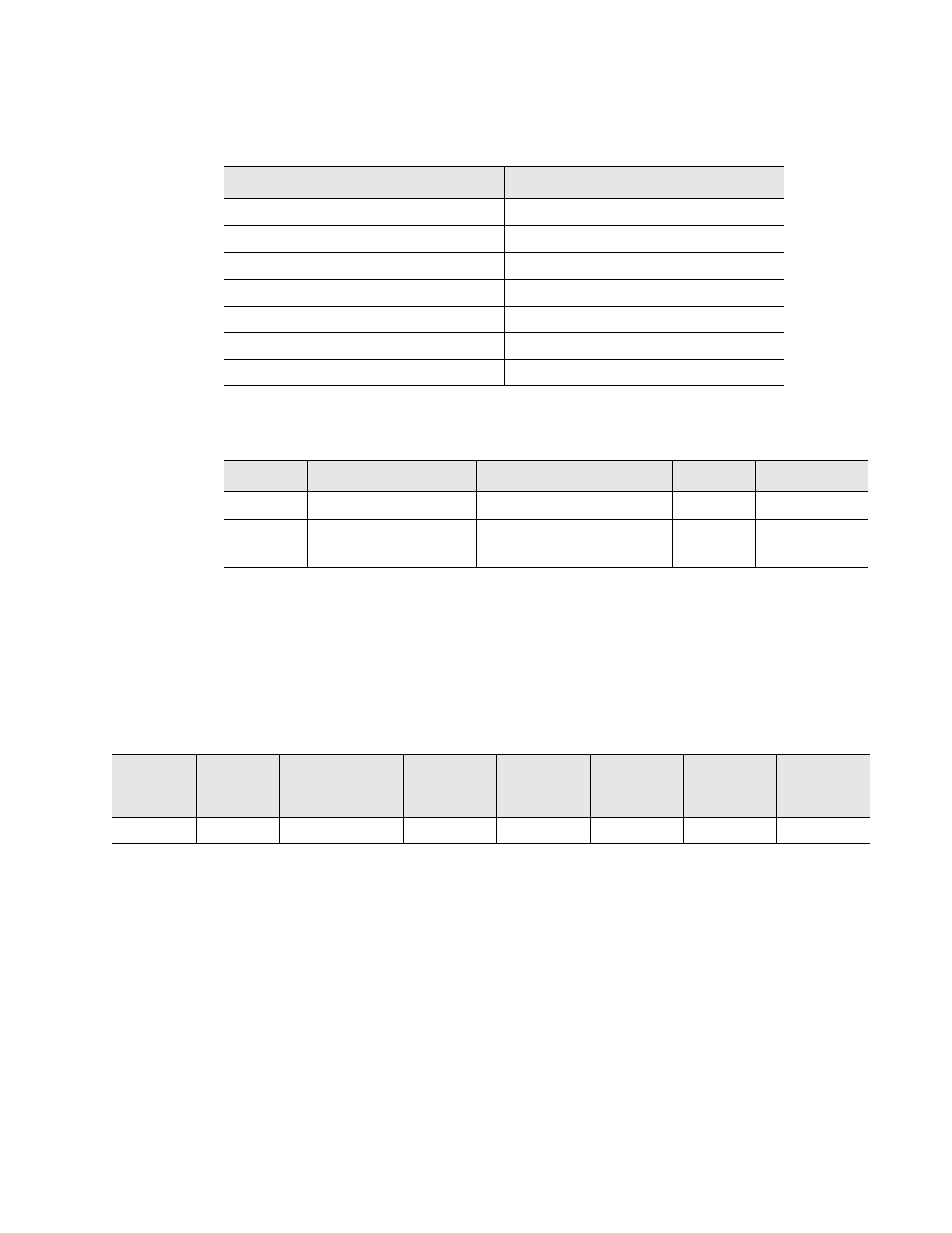
Table 4.2 Read Output Registers Packet Structure
Read Registers Request Packet
Read Registers Response Packet
Slave Address (1 byte)
Slave Address (1 byte)
03 (Function code) (1 byte)
03 (Function code) (1 byte)
Start Register (2 bytes)
Byte count (1 byte)
# of registers to read (2 bytes)
First register (2 bytes)
CRC Checksum (2 bytes)
Second register (2 bytes)
…
CRC Checksum (2 bytes)
Table 4.3 Output Registers
Register
Name
Description
Units
Range
40001
Integer Output
Register for Integer data
uint16
0-65535
42001
Float Output
* two registers need
Register for Float data
Uint32
0-65535
Table 4.4 Response Sample
Slave
Address
Function
Code
Count Bytes
of Data
Register
Data
Msb Lsb
Register
Data
Msb Lsb
Register
Data
Msb Lsb
CRC 16
“Lsb”
CRC 16
“Msb”
02
04
06
00 00 00 00 00 01 B5
A3