E-stop control panel, Cable connection panel – Smithy Ez-Trol2 User Manual
Page 14
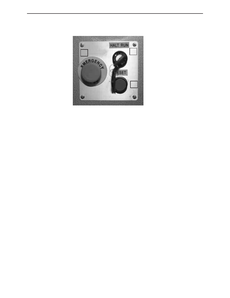
E-STOP CONTROL PANEL
Figure 4.2 EZ-Trol II E-Stop Control Panel
1. E-Stop Button – Round red mushroom head push button which when depressed until it latches
will cause the control system to go into emergency stop mode, or defeat any attempt to exit emer-
gency stop mode. This button can be released from it's depressed position by rotating the mush-
room shaped actuator.
2. E-Stop Reset – A shrouded blue momentary push button that when depressed and released will
cause the control system to exit emergency stop mode if all the following preconditions are met:
A. The ESTOP Button is released.
B. The HALT/RUN Key Switch is in the HALT position.
C. The CNC control software is running.
D. There are no faults in any monitored internal control system components.
3. Halt/Run Key Switch – This maintained action, key actuated switch has two positions:
A. HALT: When the key switch is in this position power to the spindle motor drive is discon-
nected and the control software is switched to “MACHINE OFF” mode which disables axis move-
ment and program execution control commands.
B. RUN: When the key switch is in this position all machine functions are available.
CABLE CONNECTION PANEL
The Smithy EZ-Trol II control system comes with all the necessary cables to connect it to your
machine. You will find the cables packed in with the machine, and labeled for easy connection.
1
2
3
◗
SmithyCNC EZ-Trol II Control System
8 |
Toll Free 1-800-476-4849