Basic g-code – Smithy Ez-Trol2 User Manual
Page 29
NOTE: You can tell if the machine is in E-Stop by the red colored E-Stop button on the machine.
You will need to click this to start the machine. The machine is on E-Stop when the E-Stop button
is grayed out. The reason behind this is when the machine is out of E-Stop, you can run a program
and jog around the machine. The E-Stop button is RED so as to catch attention and ready to be
activated when an emergency happens.
1
While in the Manual Tab, click the Axis Set-Up Button.
2
The Axis Home window in figure 8.2 will pop-up. Click on the square check box to the
left of “Limit Override”. An “X” will appear in the check box.
3
Click the “Ok” button in the Axis Home window, which will close the window.
4
Click the appropriate axis jog button to move the axis towards its center of travel.
When the axis is off the limit sensor, the position display numbers will turn black. You
will need to reset the axis that ran past the physical limit of travel to the home position.
NOTE: The limit override check box will only remain active for one axis movement. To jog the
same axis again or a different axis, you will need to click on the Axis Set-up button again and
recheck “Limit Override”.
BASIC G-CODE
Before machine offsets is addressed, it is important to have a basic understanding of the language
that the SmithyCNC machines use to execute the parts program. This language is called G-Code.
SmithyCNC machine use the NIST Standard language called RS274NGC. This language is
comprised of a number of codes called G-codes and M-Codes.
An M-code is a miscellaneous code. It controls an action of some specific part of the machine. A
G-code is related to a machine motion.
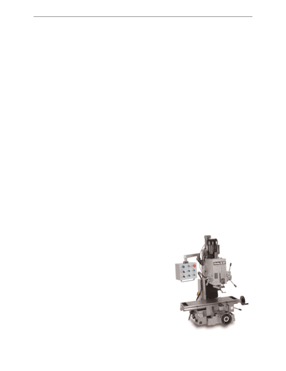
If the operator is familiar with manual machines it is easy to picture how the CNC tool works.
Imagine a work piece secured in a vise which is mounted to the table of a conventional mill and
there is an end mill in the spindle.
Hand wheels on the conventional machine allow us to
alter the relationship between the tool and the part. Turn
the X-Axis hand wheel and the work piece will move
with the table away from or toward the operator in
relation to the number of turns of the hand wheel. For
instance, turn the hand wheel of the machine one
revolution. One pitch worth of change in the relation-
ship between the tool and part will be the result of the
movement. Turn the wheel fast and the change happens
fast, turn it slow and the change happens in slow motion.
The same change happens in the Y and Z hand wheels
when they are moved. Change in the position of each
axis causes a different relationship.
Figure 8.4 A Manual Milling Machine
www.smithycnc.com
| 23