Coordinate systems & offsets – Smithy Ez-Trol2 User Manual
Page 32
NOTE: You can use the MDI entry point in the manual tab to run this program if you wish.
COORDINATE SYSTEMS & OFFSETS
A number describes the position of each axis. This number represents the distance between the
current position and the machine home position. Since a work piece might be fixture to the table in
an arbitrary position with respect to machine home, it would be convenient to shift the axis posi-
tions to coincide with a defined position on the work piece. EZ-Trol allows for nine pre-defined
coordinate systems. Each of which can have their origin offset to correspond to a point relative to
the work piece. The coordinate systems are listed on the setting page next to the G-Code word
used for selection. These are defined as: G54, G55, G56, G57, G58, G59, G59.1, G59.2 and G59.3.
NOTE: G53 can be used to refer to the machine coordinate system where the home point for each
axis is 0. For instance, if you use the block of code, G53Z0, the Z-Axis will move to its home
position. The G53 word is “non-modal”.
The objective here is to give the new user a brief introduction to offsets and to understand how they
work. We will discuss setting offset in detail in later chapters.
Notice the position of the table in figure 8.6. The depiction on the left shows machine home
position. The picture of the machine on the right shows the mid-point of the spindle is centered over
the corner of the work piece (the black block) that is mounted in the vise. This is where we offset
the G54 coordinate system. This will tell the control system that the G54 coordinate system origin
is the zero reference, starting point for the positions and distances in the program.
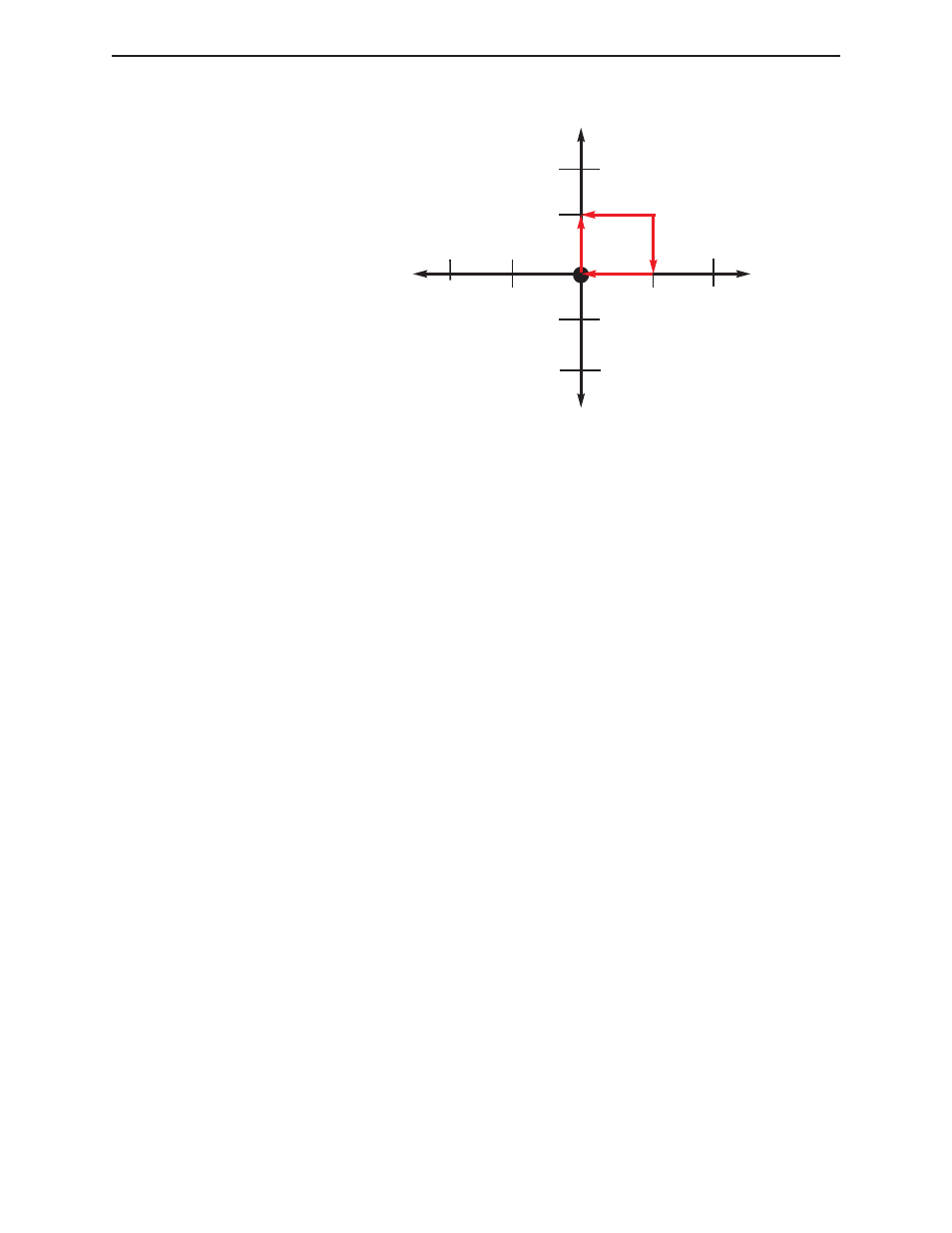
Y-Axis
X-Axis
Part
Zero
+1
+1
-1
-1
G0 Z0 X0 Y0
G1 F10 M3 S1000 Z-0.25
Y1
X1
Y1
X1
Y0
X0
G0 Z0
Figure 8.5 G-Code & Generated Path
◗
SmithyCNC EZ-Trol II Control System
26 |
Toll Free 1-800-476-4849