Electrical connections – Super Systems HP15 User Manual
Page 4
HP 15 Manual Rev A
Page 4 of 4
Electrical Connections
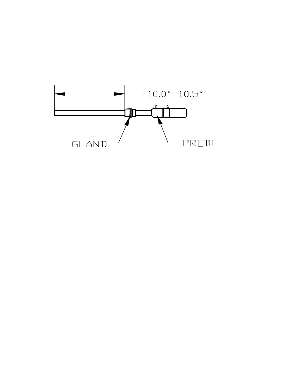
Insert the probe into the coupling at the base of the large box. It is important that the
probe is inserted at the correct depth to allow proper heating and prevent damage
to the ceramic well inside the unit. There should be between 10.0” and 10.5” between the
bottom of the adjustable 1” NPT gland and the end of the probe (see sketch below).
Once the probe has been inserted into the heater, make the necessary electrical connections at
the head of the probe. The green thermocouple wire from the electrical enclosure box should
be attached to the thermocouple connection at the head of the probe (Positive (+) = Black and
Negative (-) = Red). The sensor wire should also be attached to the probe (Positive (+) =
Black and Negative (-) = White).
This unit has been pre-configured and tested prior to shipment. To maximize the accuracy and
longevity of the Heated Probe, it is recommended that the unit be operated at 1500°F. It is
also possible to configure the HP to match the temperature of your furnace.